W61pc software installation – Wavecom W61PC V7.5.0 User Manual
Page 20
10
Setup
WAVECOM Decoder W61PC/LAN Manual V7.5
IF70#4
52.5 MHz-87.5 MHz
IF input for SAT monitoring
50 mVrms - 5 Vrms
Input impedance: 50 Ohm
EXT-DEM
Max. 12 kbps
External Demodulator Input
[0 V, +5 V] to [-12 V, +12 V]
DIG
Max. 36 Mbps, Direct Input for DSP
receivers (not yet supported)
-0.5 to +6.5 V
One or more of these inputs must be connected to the signal source(s) using a coaxial cable or a similar
shielded cable. As an example a HF receiver may be connected to an AFIF connector and a satellite receiv-
er to the IF70#4 connector.
To avoid distortion of the input signal the input voltage ranges listed above should be observed.
20 dB attenuation jumpers are located on the PCB close to the corresponding input connectors.
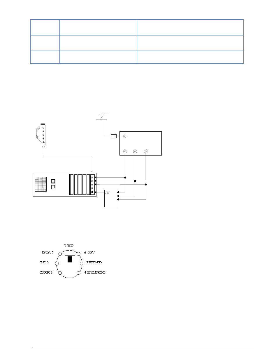
Below is an example configuration for a W61PC card setup:
The external FSK demodulator hardware is optional - it is only required if the customer wishes to use his
own demodulator hardware.
Mini-DIN Connector (EXT-DEM-IN/DIG)
W61PC Power Supply Ratings
The power supply ratings for a W61PC card are:
1.0A@+3.3V
0.4A@+12V
W61PC Software Installation
Windows’ hardware wizard can be used to install the software. Insert the WAVECOM installation disc in the
disc drive. When requested, point the wizard to the drive and start installation.
AFOUT /
EXT-DEM
AF-IN
HF-IN
10.7MHz IN
W41PC
FSK
Demodulator Box
W61PC
Board
HF or VHF Receiver
Antenna
Personal Computer (PC)
21.4MHz IN
AFOUT /
EXT-DEM
AF-IN
HF-IN
10.7MHz IN
21.4MHz IN
ANT
AF
Out
455 kHz
Out
10.7 MHz
Out