Verilink WANsuite 5230 (34-00304.F) Product Manual User Manual
Page 182
4-66
W A N s u i t e 5 2 6 0 / 5 2 3 0
It is possible that an area cannot be connected directly to the backbone. In this
case a virtual link is used. To establish or maintain the connectivity of the
backbone, virtual links can be configured through non-backbone areas.
Basically, virtual links are used to connect components that are otherwise not
connected to the backbone.
A virtual link is treated by OSPF as a point-to-point unnumbered network
joining two area border routers. The virtual link must be configured in both of
the area border routers.
A virtual link is defined by the following two parameters:
•
The Router ID of the virtual link’s other endpoint
•
The non-backbone area the virtual link goes through.
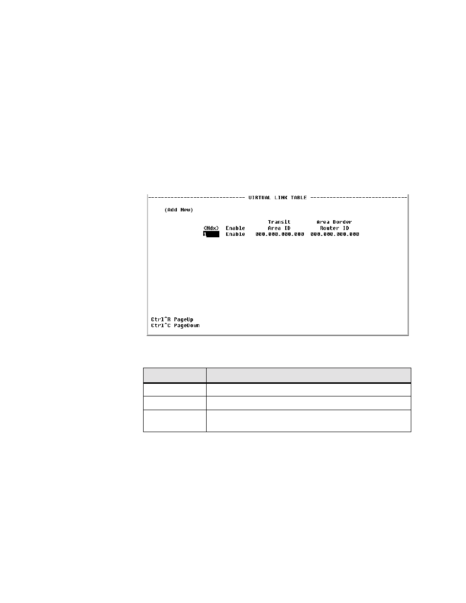
Figure 4.57
Virtual Link Table Screen
The fields displayed on the Virtual Link Table screen are described below.
Virtual Link Details Screen
This screen displays the details associated with the specific Virtual Link.
Field
Description
Enable
Enables the definition of a virtual link.
Transit Area ID
The non-backbone area the virtual link goes through.
Area Border
Router ID
The Router ID of the virtual link’s other endpoint.