Important rear connections, Chapter 3 –making connections, 17 important rear connections – Teac SX-1 Quick Start Guide User Manual
Page 17
Chapter 3 –Making Connections
TASCAM SX-1
Quick Start Guide
17
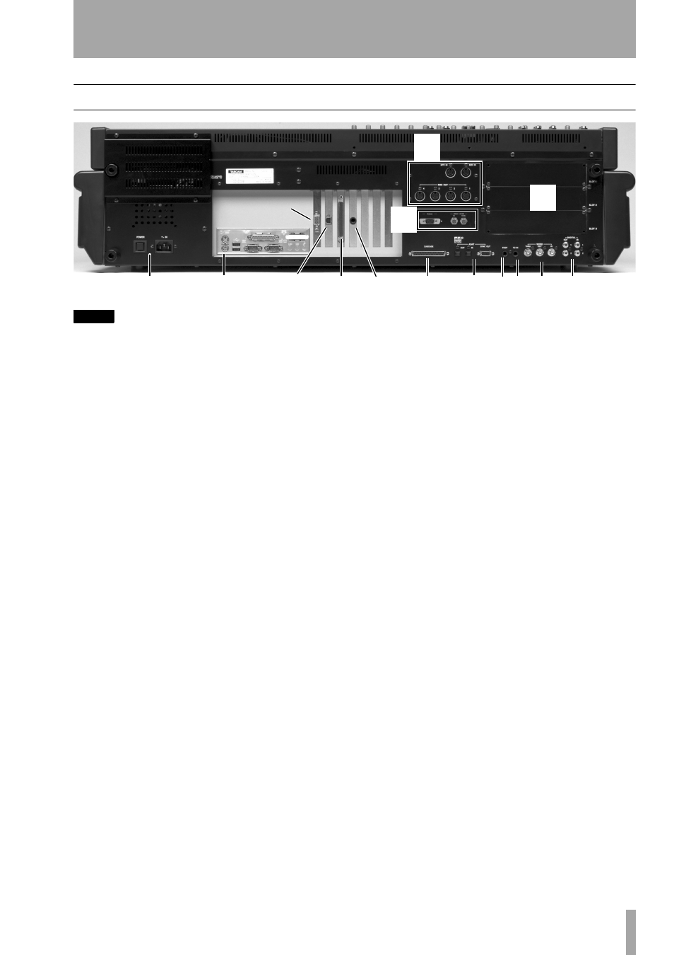
Important Rear Connections
NOTE
The position of some of the boards fitted in your SX-1
may differ slightly from the positions shown here..
There are many connections and ports on the SX-1’ s
rear. It is not necessary to understand all of them in
order to begin using the machine. For now, the areas
highlighted above (and explained below) are the
most important. (To learn more about the other con-
nections and ports, see the Owner’s Manual.)
1 Power
This is where the SX-1’s power cable
connects. An IEC Type II detachable power cable is
included with the unit. The
POWER
switch is used to
turn the unit on and off.
2 Peripheral Ports
The PS/2 keyboard and
mouse connect here. The port colored purple is for
the provided keyboard, while the green port is for the
provided mouse. The other included connections in
this section are reserved for future expansion.
3 MIDI Ports
Here you will find
MIDI OUT
Ports A, B, C, and D. Connect these ports to the
MIDI inputs of your MIDI sound modules. Also in
this area is the
MIDI IN
, where you connect the output
of your MIDI controller, and a MIDI Time Code
(MTC) jack for reading incoming MTC (see the
Owner’s Manual for more about synchronization).
See “Connecting MIDI” on page 20 for an example
of multiple MIDI devices connected to the SX-1.
4 SCSI Port
The SX1 comes equipped with a
68-pin Ultra Wide SCSI interface. You can use this
port to connect to compatible SCSI drives and
backup solutions.
5 VIDEO IN/THRU & Sony 9-pin
These
jacks are involved with synchronization. Connect a
Video sync signal (also called house sync or black-
burst) to the
VIDEO IN
.
VIDEO THRU
will pass that
same signal directly out, unaffected by any of the
SX-1’s electronics.
The Sony 9-pin connector (also known as P2) is used
for connecting to devices that adhere to that protocol.
See the Owner’s Manual for more information on
connecting P2 devices.
6 CASCADE
This connector will be used in a
future release to allow a TASCAM DM-24 console to
act as a “sidecar” for the SX-1.
7 ADAT I/O
These connectors carry eight chan-
nels of digital audio in a format commonly referred
to as ADAT lightpipe. The 9-pin D-sub connector is
used for sync/control with an ADAT-style device.
8 FOOTSWITCH
Connect a momentary-style
pedal here for remote control of recording (punching
in or out). The polarity (that is, whether the pedal is
normally open or normally closed) of the pedal is set
on the LCD
PREFERENCES
page.
9 TIME CODE IN
Connect the LTC (Longitudi-
nal Time Code, often referred to as SMPTE) output
of a device to this input. The SX-1 can chase this
incoming code.
A WORD IN/OUT/THRU
These jacks send
and receive word clock signals. The
THRU
connector
takes the signal received at the
IN
and sends out an
exact mirror, untouched by the SX-1’s electronics.
B LTC OUT
This jack allows the SX-1 to output
LTC (or SMPTE). The frame rate is determined on
the
SETTINGS
pages.
C DIGITAL I/O (SPDIF) 1 and 2
These jacks
send and receive digital audio in S/PDIF format.
They can be directly monitored in the monitoring
sections by selecting either
D-IN 1
or
D-IN 2
.
D Expansion slots
The SX-1 can have its
available I/O expanded by the addition of 8-channel
expansion cards in these slots. These cards are the
same as those used in the TASCAM DM-24 console.
1
2
4
B
6
7
8 9 A
C
3
D
5
VGA port
Ethernet
port