Analog inputs, N figure 7 – Super Systems SDS 8120 User Manual
Page 10
Super Systems Inc.
Page 10 of 104
Color Touch Screen Data Logger Operations Manual
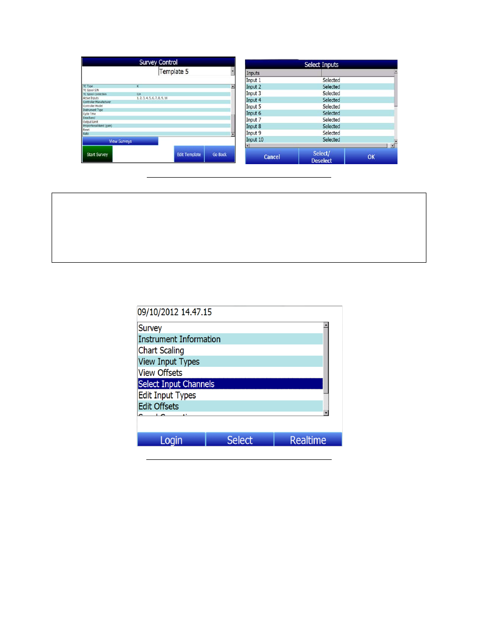
Figure 7 - Survey Control and Input Selection screens
IMPORTANT: Input channels defined in the Survey Template will override the settings in
the
Select Input Channel
option once the survey is started. All channels are being data
logged at all times. The active inputs provide real time information on the display and
evaluation for stabilization, hottest TC and coldest TC. In the event that a TC is not
selected, it can be selected when using SDS Reporter for inclusion in the final survey
report.
2. Once a survey is started, the input selection can be updated on the data logger
using the
Select Input Channels
option.
Figure 8 - Select Input Channels Option in Main Menu
Analog Inputs
The Super Systems, Inc. 31631 Analog Board contains a group of five channels isolated from the
main DC power source. The board can be connected to thermocouples, voltage sources from
20mV full scale to 1.28 Volts full scale, or 4 – 20 mA current loops. Take caution when using
current loops to avoid damaging the input (see 4 – 20 mA Current Loop connections).
Thermocouple wires can be connected directly to the terminal blocks. The thermocouple
junctions should not be grounded. If they do touch a ground reference, all thermocouples on a