Maintenance, Mod.2, Mod.3 – Partner PFT3540 B User Manual
Page 8: Mod.1, Mod.4
ENGLISH -
MAINTENANCE
Check regulary all screws and nuts for tightness
Engine: consult the instruction Manual of the engine-maker.
Wheels: axles must kept clean and sufficiently greased
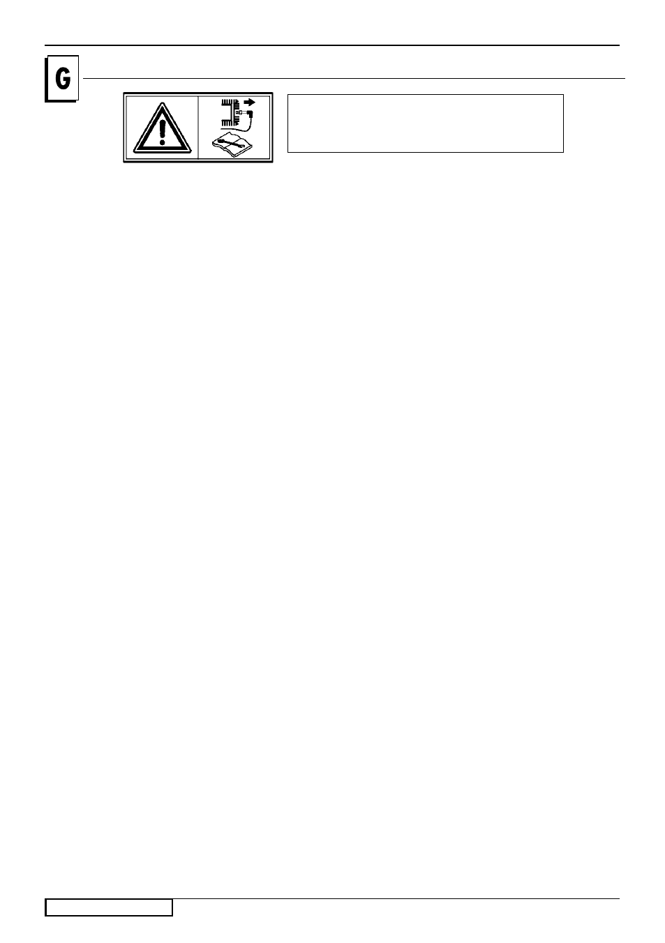
Caution! Switch off the motor and disconnect the spark
plug before undertaking any maintenance work.
MOD.2
(Fig.G
III
-G
IV
)
Clutch lever (1): When the control cable works loose,
no longer allowing the relevant coupling, the clutch cable
must be adjusted:
- Unlock lock nut (43) and unscrew screw (44) for two
complete revolutions.
- Fix position of screw (44) by tightening lock nut (43).
By acting on lever (1) make sure that cutters have
engaged. If not, repeat the operations above.
Drive blet (Z): For replacement of the belt, the following
steps must be carried out: take off the casing (T) by
unscrewing screw (S); replace the belt; then re-assem-
ble the whole.
VERSION WITH REVERSE-GEAR
Restoring of belt tension (Q): When the control cable
works loose, no longer allowing the relevant coupling,
the clutch cable must be adjusted:
- Unlock lock nut (45) and unscrew screw (46) for two
complete revolutions.
- Fix position of screw (46) by tightening lock nut (45).
By acting on lever (13) make sure that cutters have
engaged. If not, repeat the operations above.
Drive-belt (Q): For replacing the belt, take off housing (T)
by loosenisng screws (S). Then replacing the belt, take
off housing (T) by loosening screwa (S). Then replace
the belt and re-assemble the whole.
MOD.3
(Fig.G
V
-G
VI
)
Reduction gearbox (11): this unit contains approx. 150
ml oil of the SAE 20/40 grade. Check the oil level through
the filler cap (18). After 60 operation hours change the
oil. for this purpose use the respective drain plug (18)
and the filler cap (19)
Any detriment due to lack of checking the oil-lever or
incorrect oil-change are not covered by guarantee.
Clutch lever (1): When the clutch wire is too slack and
does not permit a correct engagement, introduce spring
(47) into one of the subsequent holes on plate (48).
MOD.1
(Fig.G
I
-G
II
)
Clutch lever (1): When the clutch wire is too slack and
does not permit a correct engagement, an adjustment
of the clutch wire must be carried out by introducing the
tie-bolt (41) in one of the next holes (X) of lever (12).
Drive blet (Z): For replacement of the belt, the following
steps must be carried out: take off the casing (T) by un-
screwing screw (S); replace the belt; then re-assemble
the whole.
REVERSE-GEAR
Restoring of belt tension (Q): When the clutch wire is
too slack and does not permit a correct engagement,
an adjustment of the clutch wire must be carried out
by introducing the tie-bolt (42) in one of the next holes
(Y) of lever (13).
Drive-belt (Q): For replacing the belt, take off housing (T)
by loosenisng screws (S). Then replacing the belt, take
off housing (T) by loosening screwa (S). Then replace
the belt and re-assemble the whole.
MOD.4
(Fig.G
VII
-G
VIII
)
Ball bearing lubrificate periodically the entrance shaft
to the reduction gear. For this reason, pour SAE 30
oil into oiler (A) which is located below the connection
flange.
Reduction gearbox (11): this unit contains approx.
0.500 Kg oil of the SAE 120/140 grade. Check the oil
level through the plug (18). After 0 operation hours
change the oil. for this purpose use the respective drain
plug (18) and the filler cap (19)
Any detriment due to lack of checking the oil-lever or
incorrect oil-change are not covered by guarantee.
Clutch lever (12): When the wire slackens, thus not
allowing correct engaging of the clutch, adjustment must
be effected. For this, turn screw (48) whitch is located
on the lever and on the steeldech.
Drive blet (Q): These are subject to wear; therefore
the original tensioning should be restored or the belt de
changed. For replacing te belts, proceed as follows:
- release spring (49), loosen screw (50). (Is this way,
the bowden wire of the clutch does not hold the spring
under tension).
- release the two springs (51) and remove them from their
fastening seat.
- take off the housing (5) by unscrewing the four screws
(53).
- Loosen the two screws (54) and push the belt giudes
away (55) in order to permit changing of the belt.
After replacement of the belts, remount all part.
Be careful, during the remounting operation, to place the
nylon guides (56) with the recess facing the operator. Now,
adjust tensioning of the cloutch wire.
6