Dialogic DSI SS7MD User Manual
Page 120
120
7 Configuration Command Reference
•
The logical identity of the board in the range from 0 to one less than the number of boards supported.
•
The identifier of the T1/E1/J1 Line Interface Unit (LIU) in the range from 0 to one less than the number
of LIUs.
•
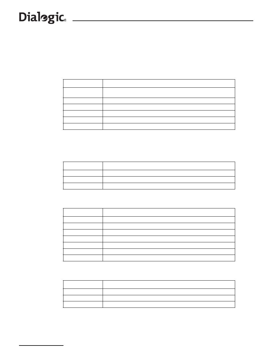
The physical interface type. The following table shows the permitted values and their meanings.
Note: The option chosen by the user must be appropriate to the actual hardware fitted, otherwise an
error status is returned.
•
The line coding technique. The following table shows the permitted values and their meanings.
•
The frame format. The following table shows the permitted values and their meanings.
•
The CRC mode. The following table shows the permitted values and their meanings.
Value
Description
1
Disabled (used to deactivate an LIU). In this mode the LIU does not produce an
output signal.
3
E1 120 ohm balanced interface
4
T1 (including J1)
5
E1 120 ohm balanced interface (preferred setting for E1 operation)
6
E1 high-impedance (for monitoring applications)
7
T1 (including J1) high-impedance (for monitoring applications)
Value
Description
1
HDB3 (E1 only)
2
AMI
4
B8ZS (T1/J1)
Value
Description
1
E1 double frame (E1 only)
2
E1 CRC4 multiframe (E1 only)
3
F4 4-frame multi-frame (T1 only)
4
D3/D4 (Yellow alarm = bit 2 in each channel (T1 only)
7
ESF (Yellow alarm in data link channel (T1 only)
8
F72/SLC96 (72-frame multi-frame) (T1 only)
9
J1 frame format (liu_type must be T1)
Value
Description
1
CRC generation disabled
2
CRC4 enabled (frame_format must be set to 2)
4
CRC6 enabled (frame_format must be set to 7)