Greenheck Vari-Flow Air Management System(476251) User Manual
Page 9
9
Vari-Flow Air Management System
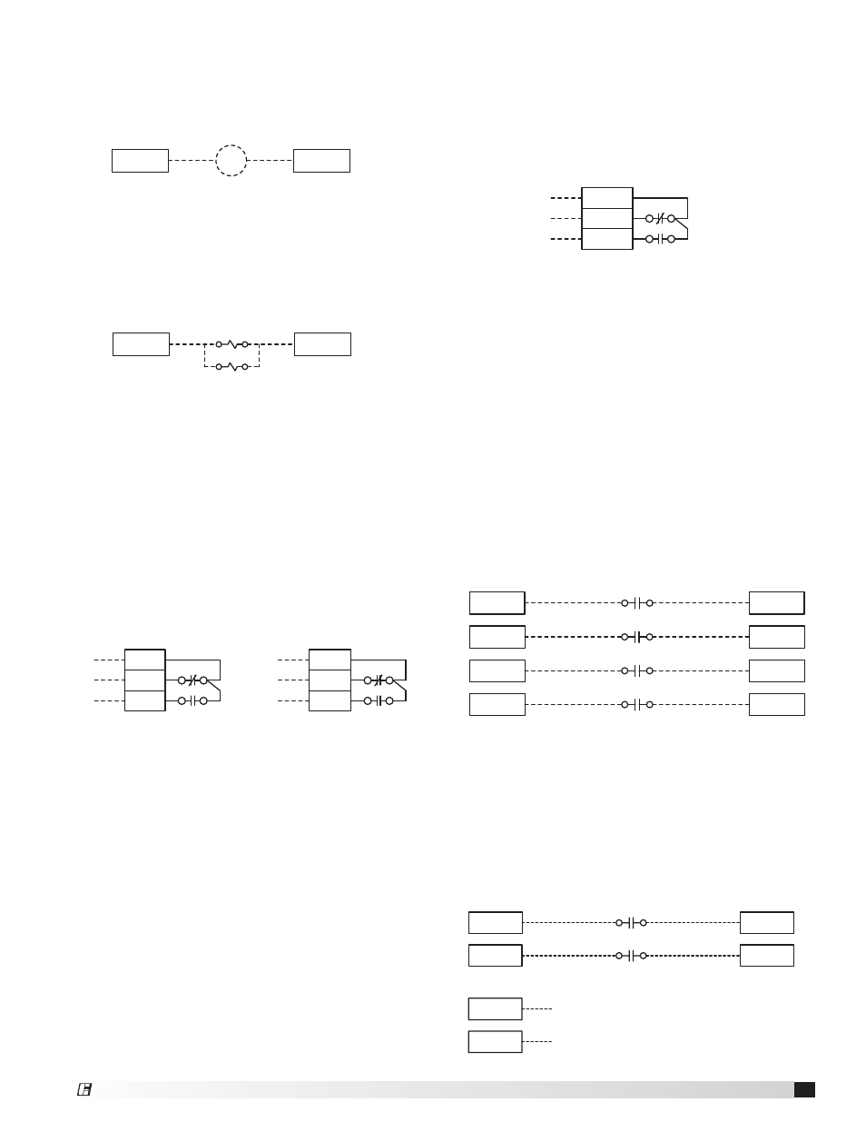
High Temperature Alarm Contacts - if equipped
• Power to common (Terminal HT-C)
• Power out, normally closed, open in high
temperature alarm (Terminal HT-NC)
• Power out, normally open, closed in high
temperature alarm (Terminal HT-NO)
Wash Interface - if equipped
• Wash input from waterwash control panel (WWCP) to
Vari-Flow (Terminals WI-1A, WI-1B)
• Wash output from Vari-Flow to Grease Grabber H
2
O
or WWCP (Terminals WO-1A, WO-1B)
• Low detergent input from Grease Grabber H
2
O or
WWCP to Vari-Flow (Terminals WD-1A, WD-1B)
Shunt Trip - if used
• 115 VAC from Vari-Flow to shunt trip breaker coil
(provided by others) (Terminals STH, STN)
Voltage across STH, STN when in fire will be 115 VAC
Voltage across STH, STN when not in fire will be 0 VAC
WASH OUTPUT
WASH FAN ENABLE/DISABLE
WASH DETERGENT
WO-1A
WO-1B
WI-1A
WI-1B
WD-1A
WD-1B
STH
STN
STB
A: Closed with power at H & N and high temperature
alarm inactive, closed with no power
B: Open with power at H & N and high temperature
alarm active, open with no power
HT-C
HT-NC
HT-NO
R13
22
24
21
A
B
(Can be used for shunt trip, alarms, etc.)
AP-1A
AP-1B
AIR PROVING SUPPLY FAN 1
AP-2A
AP-2B
AIR PROVING SUPPLY FAN 2
AP-3A
AP-3B
AIR PROVING SUPPLY FAN 3
AP-4A
AP-4B
AIR PROVING SUPPLY FAN 4
Spare Fire Relay Contacts - if equipped
• Power to common (Terminal C3)
• Power out, normally open, closed in fire
(Terminal NO3)
• Power out, normally closed, open in fire
(Terminal NC3)
• Power to common (Terminal C4)
• Power out, normally open, closed in fire
(Terminal NO4)
• Power out, normally closed, open in fire
(Terminals NC4)
C3
NO3
NC3
C4
NO4
NC4
R6
12
14
11
R6
22
24
21
A
B
A
B
(Can be used for shunt trip, alarms, etc.)
A: Open with power at H & N and fire system armed closed on
fire or no power
B: Closed with power at H & N and fire system armed open on
fire or no power
Electric Gas Valve with Gas Reset - if equipped
• 115 VAC from Vari-Flow to gas solenoid
(Terminals SVH, SVN)
Voltage across SVH, SVN when in fire will be 0 VAC
Voltage across SVH, SVN when not in fire and turn on
will be 115 VAC
SVH
SVN
SV2
SV1
Airflow Proving Switch(es) (provided by others) - if
equipped
• Common and normally open from supply fan 1 air
proving switch to Vari-Flow (Terminals AP-1A, AP-1B)
• Common and normally open from supply fan 2 air
proving switch to Vari-Flow (Terminals AP-2A, AP-2B)
• Common and normally open from supply fan 3 air
proving switch to Vari-Flow (Terminals AP-3A, AP-3B)
• Common and normally open from supply fan 4 air
proving switch to Vari-Flow (Terminals AP-4A, AP-4B)
NOTE: Airflow proving switch(es) are not provided with
the Vari-Flow system.
®