G. service, H. manufacturer – Greenheck Vari-Flow Air Management System(476251) User Manual
Page 21
21
Vari-Flow Air Management System
The Service Settings menu allows the user to change the default Service
Password (1000), save and restore default parameters, and adjust probe values.
NOTE: The manual adjustment of these input and/or outputs should only be
adjusted in the event of troubleshooting. Change parameters to the advice of
factory personnel.
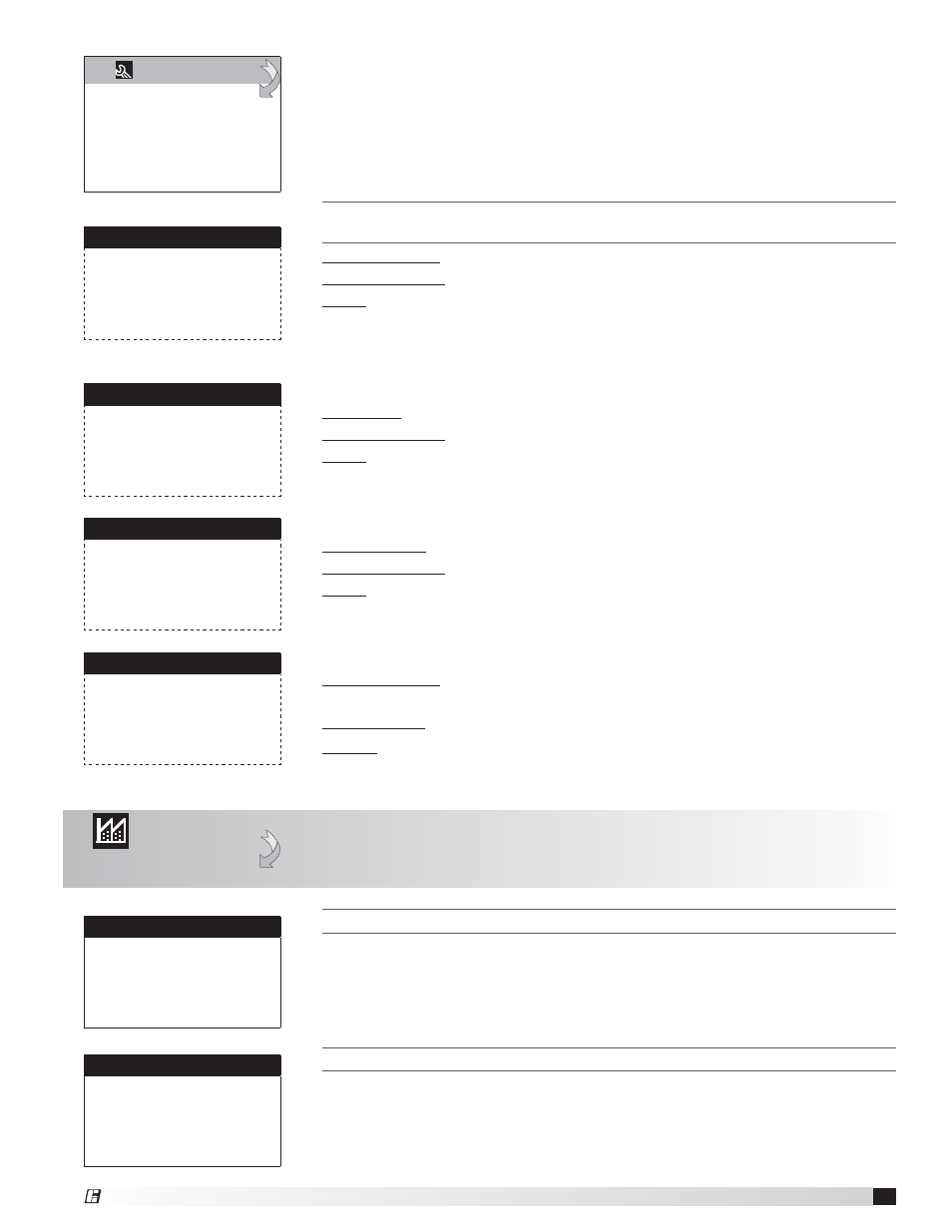
G.
Service
d. Manual Management
a. Analog Inputs
b. Digital Inputs
c. Relay Outputs
d. Analog Outputs
Manual Relay: Allows the user to override the digital input for troubleshooting.
Manual Position: The value to force the output to when in an override state.
Value: The current state of the relay output.
Similar screens appear for all additional controller digital inputs.
Relay Output
Manual Relay 1:
OFF
Manual Position:
OFF
Relay 1 Status:
OFF
Manual Control: Allows the user to override the analog output for
troubleshooting.
Manual Value: The value to force the input to when in an override state.
Output: The current value of the analog output.
Similar screens appear for all additional controller analog inputs.
Analog Output
Mode: Auto
Manual Value:
0.00vdc
Output: 5.00vdc
H. Manufacturer
a. Configuration
The Configuration menu allows the user to change the units, enable Scheduling,
Holidays, expansion I/O and change Field Card settings. Users are welcome to enable
Scheduling and Holidays. However, configuration changes and expansion I/O enabling
are to be done under factory advice only!
T
HIS
SCREEN
DISPLAYS
AND
ALLOWS
ADJUSTMENT
OF
THE
UNIT
SETTINGS
.
These settings have been set from the factory to operate the components selected
with the control system. When troubleshooting, refer to the wiring diagram sent
with the unit (located on the control center door).
Configuration
Temperature Units:
°F
Force Clock Enable:
OFF
Clock Mode:
24h
Disable Buzzer:
OFF
Startup Delay:
5s
T
HIS
SCREEN
DISPLAYS
AND
ALLOWS
ADJUSTMENT
OF
THE
UNIT
ON
/
OFF
SETTINGS
.
These settings have been set from the factory to operate the components selected
with the control system. When troubleshooting, refer to the wiring diagram sent
with the unit (located on the control center door).
Configuration
Enable Unit On/Off
By digit input:
OFF
By Supervisor:
OFF
By pLAN network:
OFF
By Schedule:
OFF
T
HE
P
ROBE
A
DJUSTMENT
MENU
ALLOWS
THE
USER
TO
CALIBRATE
SENSOR
PROBES
WITH
AN
OFFSET
VALUE
.
Manual Control: Allows the user to override the analog input for troubleshooting.
Manual Position: The value to force the input to when in an override state.
Value: The current value of the analog input.
Similar screens appear for all additional controller analog inputs.
Analog Input
Temperature 1
Manual Control B001
OFF
Manual Position:
0
Value: 80.0°F
Manual DI: Allows the user to override the digital input for troubleshooting.
Manual Position: The value to force the input to when in an override state.
Value: The current state of the digital input.
Similar screens appear for all additional controller digital inputs.
Digital Input
Remote On/Off
Manual DI 1:
OFF
Manual Position:
CLOSED
DI 1 Status:
Closed
®