Touch screen mounting, Electrical connections, If equipped touch screen mounting diagram – Greenheck Vari-Flow Air Management System(476251) User Manual
Page 5
5
Vari-Flow Air Management System
NOTE
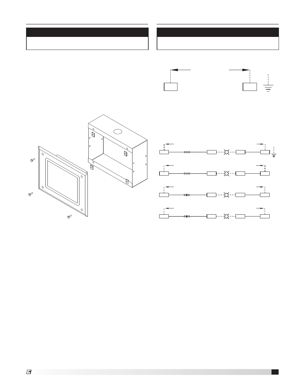
The touch screen may be factory mounted. If so,
continue to the Electrical Connections section.
Touch Screen Mounting
- if equipped
Touch Screen Mounting Diagram
CONTROL INPUT:
115 VAC, 15 AMPS FROM BREAKER
H
N
G
1. For systems with remote controls or touch screen,
two 35, 75, or 150 foot sets of cables are supplied to
connect the touch screen to the controls. The cables
are plenum rated and do not need to be run through
conduit unless required by local codes. If the keypad
is to be mounted further away than the cable that is
received, additional cable will be needed. Additional
cables are available at the lengths mentioned above.
NOTE
All wiring of electrical equipment must be done to
meet NEC and local codes.
Electrical Connections
Power for Lights
• 115 VAC, power for hood lights, one per light circuit
(Terminals H1, N1 | H2, N2 | H3, N3 | H4, N4)
• 115 VAC, power to lights, one per light circuit
(Terminals B1, W1 | B2, W2 | B3, W3 | B4, W4)
Power for Vari-Flow Cabinet
• 115 VAC, power for controls (Terminals H and N)
R1
HOOD LIGHT
RELAY 1
14
11
HOOD LIGHT(S)
LIGHT CIRCUIT 1: 115 VAC, 15 AMPS FROM BREAKER
H1
W1
B1
EACH CANOPY LIGHTING CIRCUIT MUST NOT EXCEED 15A TOTAL CURRENT
N1
WH 14GA
BK 14GA
BK 14GA
G
R2
HOOD LIGHT
RELAY 2
14
11
BK 14GA
HOOD LIGHT(S)
H2
B2
N2
W2
LIGHT CIRCUIT 2: 115 VAC, 15 AMPS FROM BREAKER
WH 14GA
BK 14GA
R3
HOOD LIGHT
RELAY 3
14
11
HOOD LIGHT(S)
H3
B3
N3
W3
LIGHT CIRCUIT 3: 115 VAC, 15 AMPS FROM BREAKER
WH 14GA
BK 14GA
BK 14GA
R4
HOOD LIGHT
RELAY 4
14
11
HOOD LIGHT(S)
H4
B4
N4
W4
LIGHT CIRCUIT 4: 115 VAC, 15 AMPS FROM BREAKER
WH 14GA
BK 14GA
BK 14GA
®