Line, Load, Modbus vfd mua unit – Greenheck Vari-Flow Air Management System(476251) User Manual
Page 7: Mua - vfd in unit, Make-up air vfd in vari-flow wiring
7
Vari-Flow Air Management System
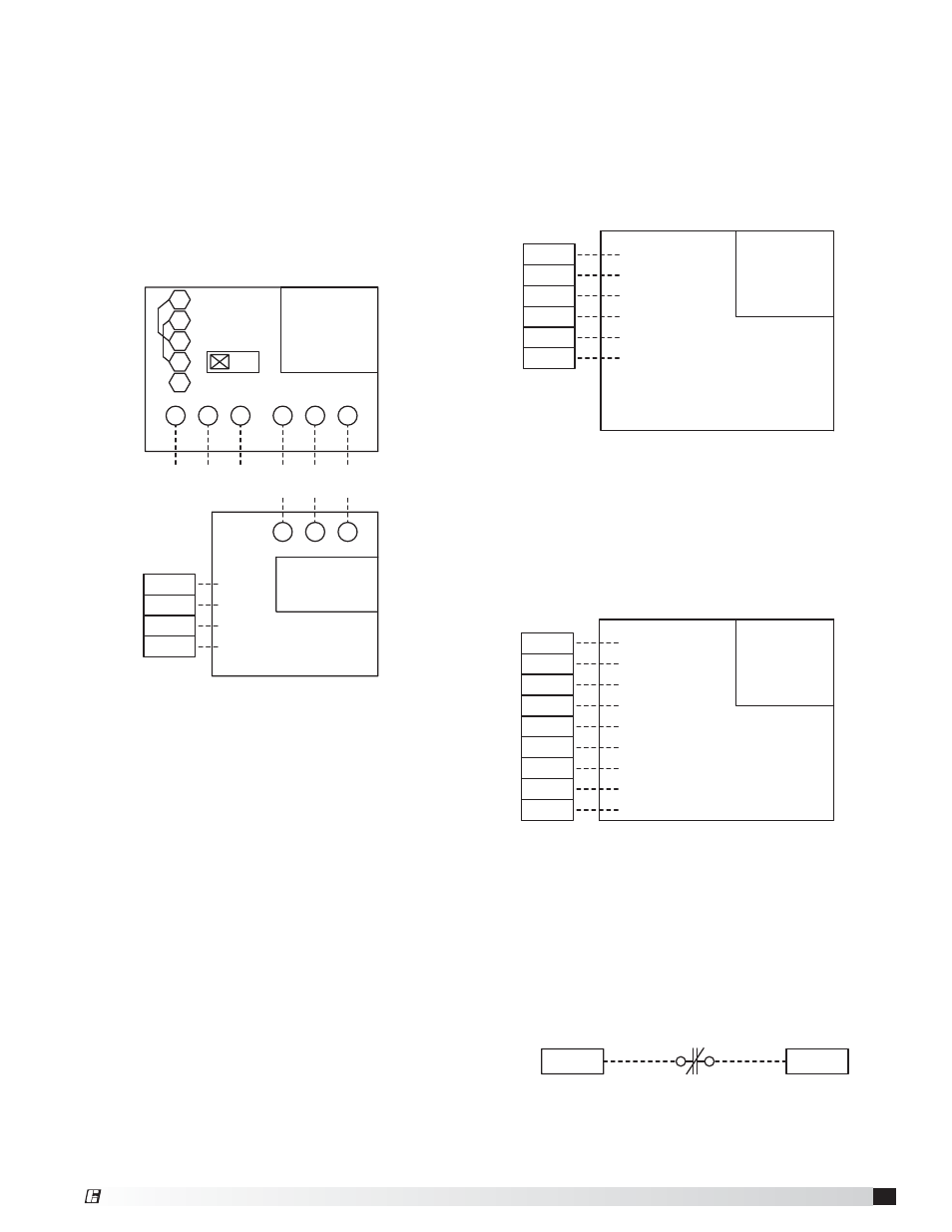
Fire System Microswitch
• Fire system microswitch common to Vari-Flow
(Terminal C1)
• Fire system microswitch normally closed contact to
Vari-Flow (Terminal NC1)
C1
NC1
Make-Up Air VFD in Vari-Flow Wiring
- if equipped
• 24 VAC run command from Vari-Flow to make-up air
unit (Terminals S__-42, S__-43)
• Tempering status from Vari-Flow to make-up air unit
(Terminals S__-44, S__-45)
• Line power to VFD input, bottom left of VFD
(Terminals L1, L2, L3)
• Load power from VFD output, bottom right of VFD to
make-up air disconnect (Terminals T1, T2, T3)
Make-up air unit requires separate 115 VAC control
power circuit.
Make-Up Air VFD in Make-Up Air Wiring
- if equipped
• 24 VAC run command from Vari-Flow to make-up air
unit (Terminals S__-42, S__-43)
• Tempering status from Vari-Flow to make-up air unit
(Terminals S__-44, S__-45)
• 0-10 VDC speed reference from Vari-Flow to
make-up air unit (Terminals S__-46, S__-47)
Power for make-up air goes directly to make-up air unit.
This is an example of Supply Fan 1 being a
make-up air with VFD in the Vari-Flow.
S+
S-
R+
L3
LINE
R-
IG
L2
L1
T3
LOAD
T2
T1
VFD-F2-S
MARK: MUA - VFD
VAV
VOLT/PH
HP
MODBUS VFD
ADDRESS: X
S2
TEMPERING STATUS
S2-42
S2-43
S2-44
S2-45
TEMPERING STATUS
MAKE UP AIR UNIT
CONTROL WIRING
DISCONNECT IN UNIT
MARK: MUA - VFD
VAV
F2-S
SEPARATE CONTROL POWER
TO UNIT REQUIRED
COM
RUN
24 VAC
MODBUS VFD
MUA
UNIT
THIS LAST VFD IN
MODBUS LINE MUST
HAVE THE END OF
LINE RESISTOR
SWITCHED ON
ON
This is an example of Supply Fan 1
being a make-up air with VFD in the make-up air unit.
24 VAC COM
24 VAC RUN
TEMPERING STATUS
S1-42
S1-43
S1-44
S1-45
S1-46
S1-47
SPEED REFERENCE +
SPEED REFERENCE -
NOTE: CONTROL POWER FOR
MUA GOES DIRECTLY FROM
BREAKER PANEL TO MUA.
TEMPERING STATUS
(0-10 VDC)
VFD-F2-S
MARK: MUA - VFD
MUA
VOLT/PH
HP
VFD IN MUA UNIT
MUA
- VFD IN UNIT
Auto Tempering - if equipped
• Auto Heat/Cool enable
(Terminals S1-R, S1-W1, S1-Y1)
This is an example of Supply Fan 1 with auto tempering.
24 VAC COM
24 VAC RUN
TEMPERING STATUS
S1-42
S1-43
S1-44
S1-45
S1-46
S1-47
SPEED REFERENCE +
SPEED REFERENCE -
NOTE: CONTROL POWER FOR
MUA GOES DIRECTLY FROM
BREAKER PANEL TO MUA.
TEMPERING STATUS
(0-10 VDC)
VFD-F2-S
MARK: MUA - VFD
MUA
VOLT/PH
HP
VFD IN MUA UNIT
MUA
- VFD IN UNIT
S1-Y1
S1-R
COOL
CONTROL COMMON
S1-W1
HEAT
®