Setup, Tools and accessories, Installation instructions – Gasboy FHO Pods User Manual
Page 19: Setup 2.6.1. tools, Accessories, Installation, Instructions, Figure 2-4. mifare pod – connectors, Table 2-2. mifare pod installation kit items
2.6. SETUP
This section provides setup and configuration instructions for the MiFare Pod.
2.6.1. Tools and Accessories
The MiFare Pod is provided with an installation kit, described in Table 2-2.
Table 2-2. MiFare Pod Installation Kit Items
Orpak P/N
Name
Quantity
811010980 MiFare Pod Unit
1
811307100 Power Supply 115/230V-15V-1A
1
819302950 Power Cable, 115V
1
819136700 RS-232 Harness
1
2.6.2. Installation Instructions
The MiFare Pod is linked to the FHO PC. The following paragraph provides step by step
instructions for the installation of the MiFare Pod.
1. Place the MiFare Pod in the office next to the HO PC
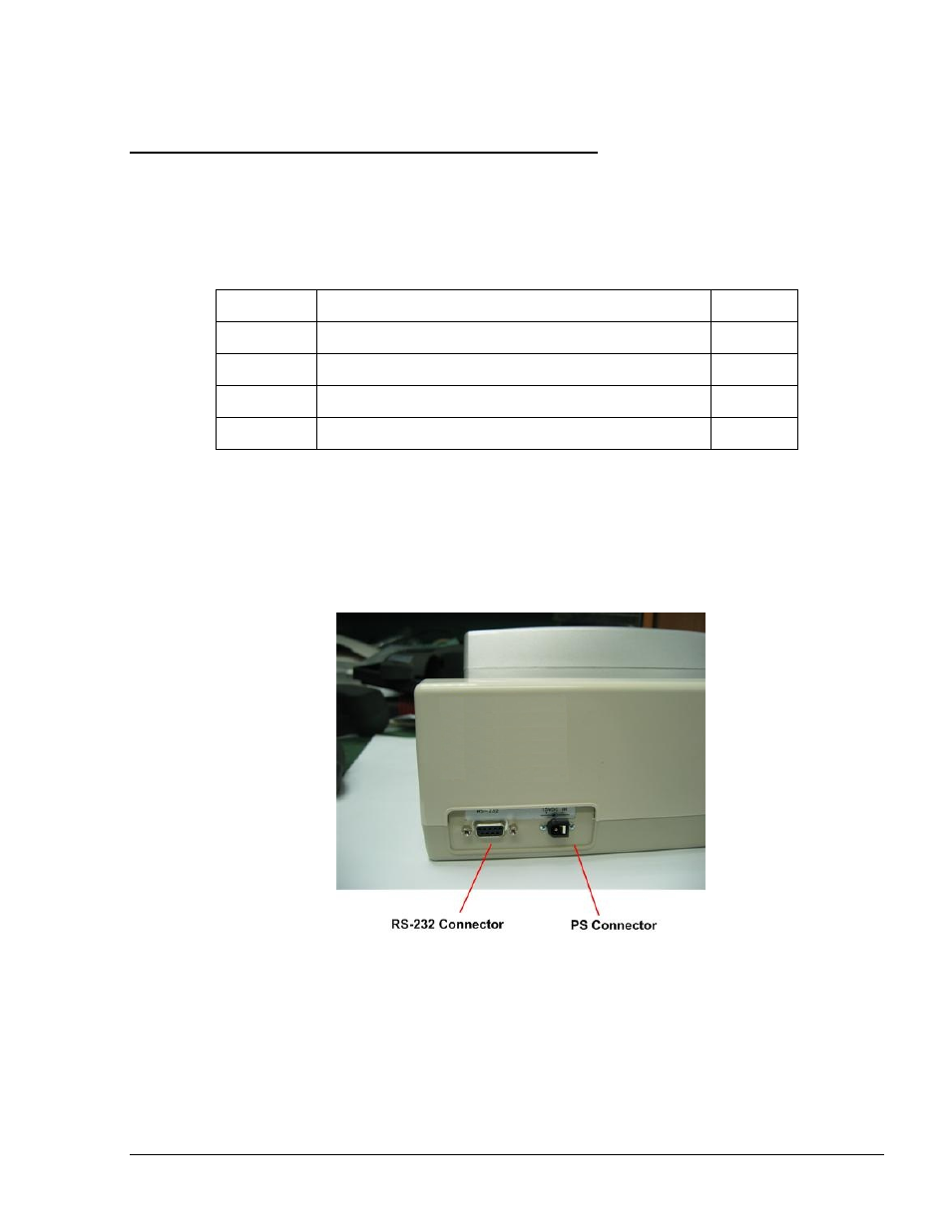
2. Connect MiFare Pod to power supply. The Pod connectors are shown in Figure 2-4
Figure 2-4. MiFare Pod – Connectors
The MiFare Pod displays the following message (see Figure 2-5):
FHO Pods User’s Manual
17