Gasboy Fuel Point Reader User Manual
Page 36
GASBOY Fuel Point System
4-10
03/28/03
Adding Comm. Port 2 to Series 1000 Using the C06823 Kit
The C06800 and C06801 Fuel Point systems contain a C06823 kit for adding the Comm. Port 2
cable to the Series 1000. The contents of the C06823 kit are shown below.
Qty.
Part Number
Description
1
C05918
Cable, Auxiliary Comm.
1
C35621
Bracket, Aux. Comm.
2
C04030
Screw, 8-32 x 3/4
1
C01695
Decal, "AUX. 12345 PORT"
1
C08938
Terminal Block Jumper
1.
Remove the housing wrapper and access panels on the Series 1000.
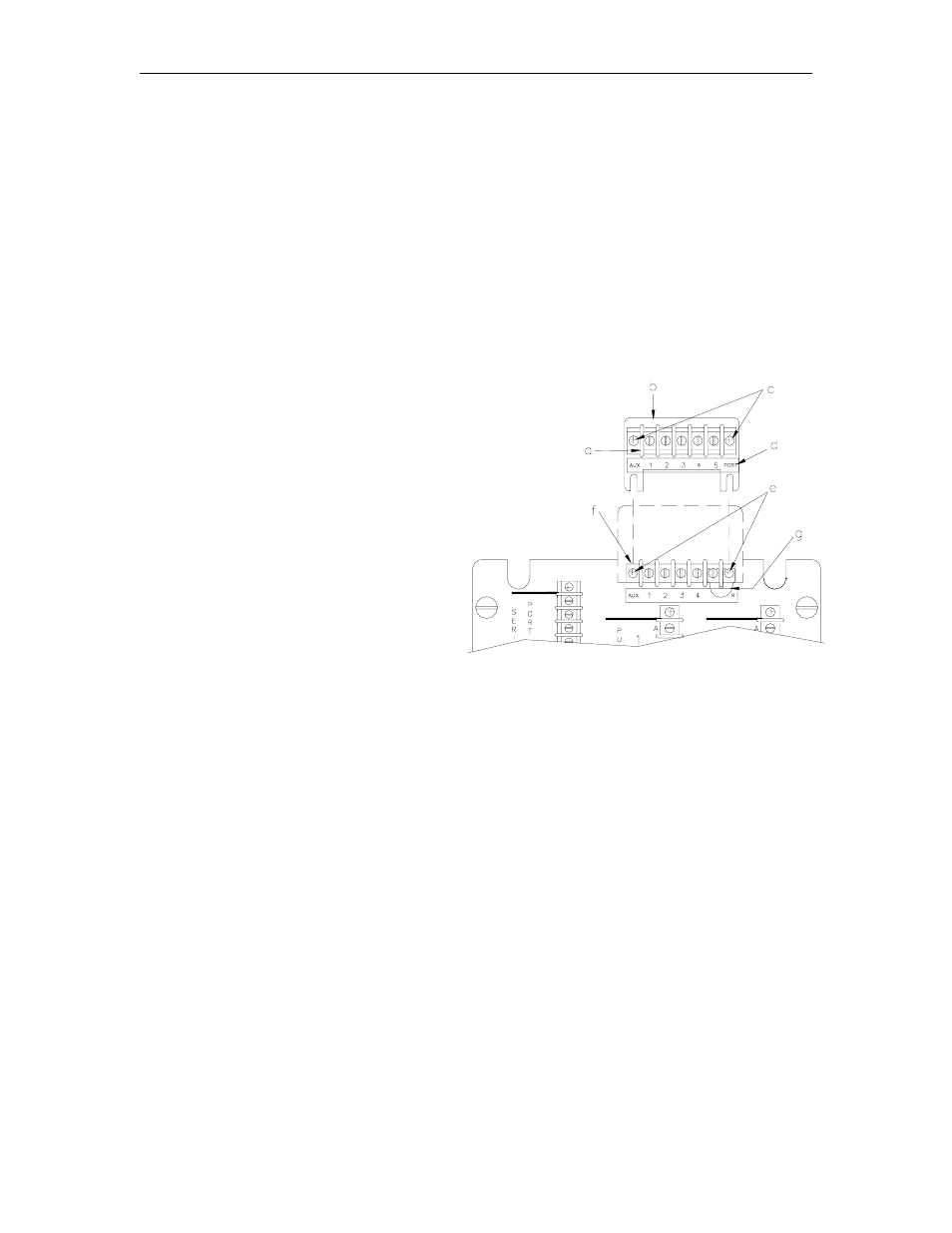
2.
Attach the C05918 terminal block and
cable assembly (a) to the C35621
bracket (b) using two C04030 screws
(c). When installing the assembly, the
red wire from the terminal block must
be on the left.
3.
Place the C01695 decal below the
terminal block (d).
4.
Loosen, but do not remove, the two
screws (e) holding the Auxiliary Comm.
Port 1 terminal block to the pedestal.
Place the C35621 bracket assembly
behind the terminal block (f) in the
pedestal.
5.
Add the C08938 jumper (g) to the two
right-most screws of the Fuel Point
(bottom) terminal block.
6.
If the Series 1000 was previously interfacing to the tank monitor, the tank monitor's
communication wiring is on the bottom terminal block. You must move the tank monitor
wiring from the bottom terminal block to the top one. The other end of the top terminal block
cable must plug into P4 on the Auxiliary Comm. PCB (h). Note that P4 is an RS-232 port. If
the tank monitor was previously connected to P3, also RS-232, then no re-wiring is needed.
If the tank monitor was previously connected to P2, RS-422, you must consult your tank
monitor manual to see what changes are required for RS-232 communications. When
routing the cable to the Auxiliary Comm. PCB, pass it through the large nylon bushing where
the head joins the post. Pass it under the MPU PCB so it comes out in front of the boards.