Installing the t-meter module and cables – Gasboy M06875K00X User Manual
Page 9
MDE-4556 Gasboy ATC Kits M06875K00X Installation Manual • July 2006
Page 9
Installation
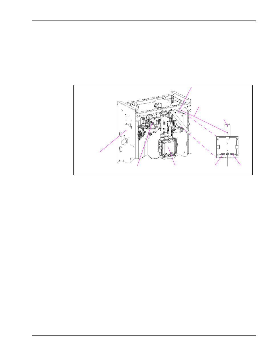
Installing the T-Meter Module and Cables
The cables used in this section are included with the T19405-G4 T-Meter module.
1
Install the T-Meter module onto two clinch studs located on the inside of the side column
(
, install on either side).
Note: Locate T-Meter module so cables can reach appropriate probe connectors.
Figure 2: Example of Installed T-Meter Module
2
Connect the T-Meter module cables as follows (
• J200 connector on first R20148-G3 cable to P200 connector on T19405-G4 module
• PTP1 connector on first R20148-G3 cable to RTD Probe A1 connector
• J202 connector on second R20148-G3 cable to P202 connector on T19405-G4 module
• PTP5 connector on second R20148-G3 cable to RTD Probe B1 connector
• J201 connector on R20147-G1 cable to P201 connector on T19405-G4 module
Note: The P1S connector on the R20147-G1 cable is not connected at this time; it will be
connected in the
Installing I.S. Barrier Assembly
junction box
side column
P200
P201
P202
lower clinch stud location
T19405-G4 T-Meter Module
upper clinch stud
mounting hole
probe location
(another on other side)