Completing installation, Completing, Figure 8 – Gasboy M06875K00X User Manual
Page 16: Warning
Installation
Page 16
MDE-4556 Gasboy ATC Kits M06875K00X Installation Manual • July 2006
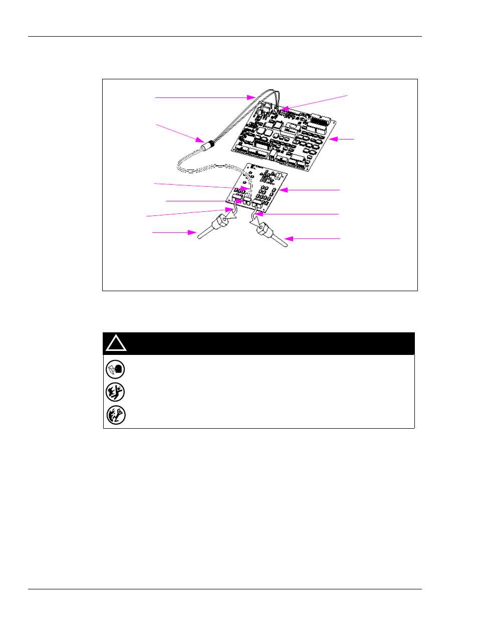
Figure 8: ISB to ATC Controller and T-Module Assembly Connections
Note: For simplification, the J1S-to-P1S and junction box connections are not shown.
Completing Installation
1
Place conversion labels, nameplates, any extra cable ties, and additional hardware on upper
shelf.
2
Securely attach junction box cover with all bolts using the 1/2-inch socket wrench.
3
Turn power ON (including lights) as follows:
• Reconnect multiple disconnects.
• Turn system circuit breakers on.
• Turn on associated STP power.
• Turn on power to all pumps/dispensers on same isolation relay, if used.
• Turn on system battery.
• Remove OSHA lock-outs and tag-outs.
• Turn on shear valve.
side B probe
4
side A probe
4
T19428-G1 ISB
Assembly
1
J307 to P307
R20147-G1
3
T19405-G4 T-Meter
Module Assembly
3
T20569-G1 ATC
Controller
2
J201 to P201
3
R20148-G3
3
R20148-G3
3
R20128-G1
(existing)
Notes:
1. Installed in
“Installing I.S. Barrier Assembly” on page 11
.
2. Installed in
“Installing ATC Controller Board” on page 12
.
3. Installed in
“Installing the T-Meter Module and Cables” on page 9
.
4. Installed in
“Installing Filter Manifold and Probe” on page 7
.
Spilled or leaking fuels in the vicinity of electrical junction boxes can be hazardous if
boxes are not properly closed.
Serious fire/explosion and injury/death could result.
Replace all bolts and tighten junction box cover before turning on unit AC power. Do not
use gaskets on junction box covers.
!
WARNING
!