Gasboy M06875K00X User Manual
Page 8
Installation
Page 8
MDE-4556 Gasboy ATC Kits M06875K00X Installation Manual • July 2006
2
Unbolt and carefully remove current M04607B001 Valve and Filter Manifold.
3
Note orientation of check valve assembly located between manifold and meter.
4
Discard two O-rings located on each side of check valve assembly.
5
Clean meter surface where new M04607B003 Valve and Filter Manifold will be mounted.
6
Place new Q10068-09 O-Ring (1.234-inch I.D.) into meter opening.
7
Place new Q10068-14 O-Ring (1.609-inch I.D.) into opening of new M04607B003 Valve and
Filter Manifold.
8
Properly orient the check valve between the meter body and new M04607B003 Valve and
Filter Manifold and bolt the new manifold to the meter.
9
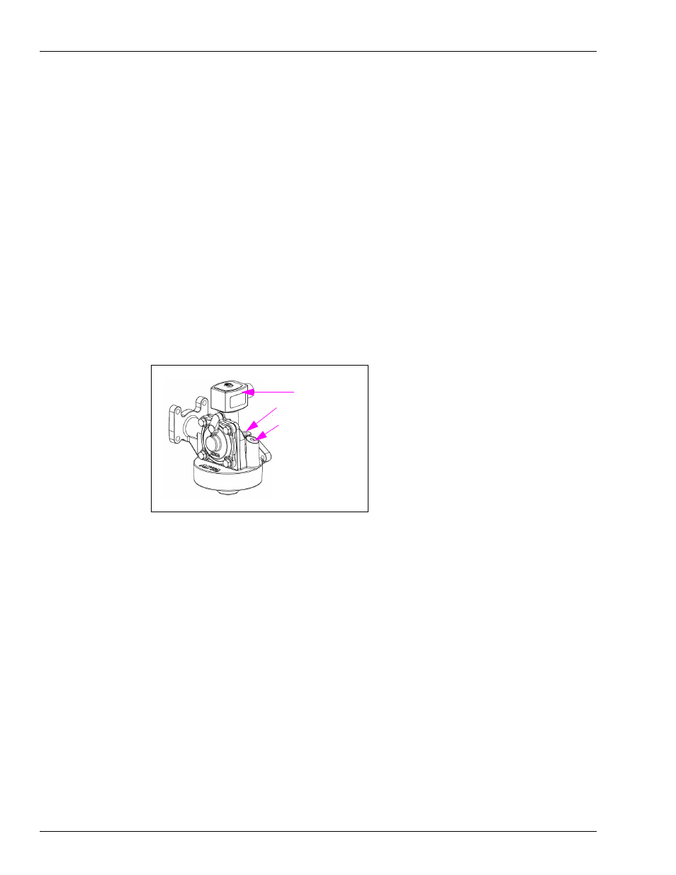
Carefully remove the plugs from the ATC ports (
Figure 1: M04607B003 Valve and Filter Manifold
10
Insert the Q13131-01 RTD Probe Assembly into the RTD probe port on the filter manifold.
Note: The connection to the probe assembly will be made in the
Installing Filter Manifold and
section which follows.
11
Insert the new Q13130-01 Thermowell into the Thermowell port in the filter manifold.
12
Fully insert the new R19457 High-Capacity Strainer Insert into the filter cavity of the
manifold with the pull tabs properly oriented.
13
Install a new filter onto the new filter manifold.
14
Replace the connection from the coil on the old manifold with the connection from the coil on
the new maniold.
15
If installing the M06875K002 - ATC Kit for Two-Sided Unit, repeat steps
through
other side of the dispenser.
Thermowell port
coil
RTD probe port