Figure 2 – Gasboy Atlas Discharge User Manual
Page 7
MDE-4503 Atlas Discharge and Valve Conduit Retrofit Kit • July 2005
Page 7
Installing the M06228K001 or M06228K002 Kit
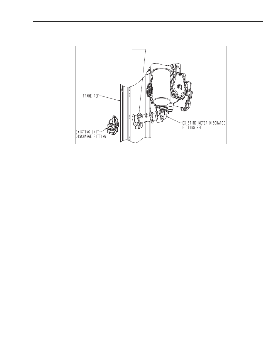
Figure 2: Discharge Line Removal
6
Remove the (2) bolts connecting the unit discharge fitting to the frame.
7
Remove the unit discharge fitting and slide copper discharge tube out of the unit. (Retain the
unit discharge fitting and one of the formed flanges. Discard the copper tube, o-rings, bolts and
the other formed flange.)
If there are two meters, disconnect and remove the second discharge line in the same manner
as steps 5, 6, and 7.
To remove the valve filter manifold: (see
8
Tape meter/computer universal joint to retain the “dumb-bell” looking part, for units using the
mechanical meters. (Dumb-bell may be displaced during disassembly/reassembly.)
HINT: It may be desirable to tape the meter shaft connection to the pulser drive connector
mounted on the lower air gap plate on electronic units.
9
Loosen the (3) bolts securing the meter to the meter bracket.
10
Remove the (2) bolts connecting the feedline to the valve/filter manifold. Retain the bolts and
the 0-ring.
11
Remove the (4) bolts connecting the valve/filter manifold to the meter and remove the valve/
filter manifold along with the connected coil conduit. Remove the conduit from the coil.
Remove the union half from the conduit. Retain the valve/filter manifold, bolts, o-rings and
the union half. Discard the conduit.
12
Repeat steps 8 through 11 if there are two meters.
13
If the unit has internal hose retrievers, remove the retriever reel(s) and bracket(s). Retain the
reel and hardware. Discard the bracket.
EXISTING UNIT DISCHARGE
FLANGE