Figure 6 – Gasboy Atlas Discharge User Manual
Page 11
MDE-4503 Atlas Discharge and Valve Conduit Retrofit Kit • July 2005
Page 11
Installing the M06228K001 or M06228K002 Kit
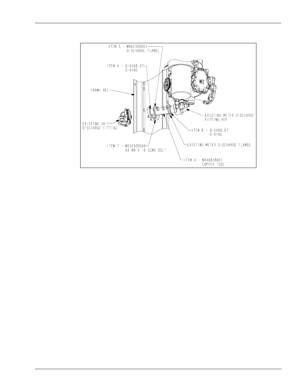
Figure 6: Discharge Flange Replacement.
32
Insert (1) o-ring (
, Item 6) over the tube end.
33
Slide the new discharge flange (
, Item 5) over the opposite end of the copper tube so
that the o-ring will be captured within the formed o-ring cavity of the flange. Insert (1) o-ring
(
, Item 6) over the tube end.
34
Insert the copper tube into the existing meter discharge fitting (
). Slide the o-ring and
flange to the face of the meter discharge fitting and insert (2) SEMS bolts (
, Item 7.
Do not tighten.
Note: Existing flange goes to the meter side.
35
Insert the existing unit discharge fitting on the other end of the copper tube. Insert (2) SEMS
bolts (
, Item 7) through the mounting holes in the frame to mount the existing unit
discharge fitting to the frame. Tighten the (2) bolts.
36
Slide the o-ring and the new flange to the face of the unit discharge fitting and insert (2) SEMS
bolts (
, item 7.
Note: Ensure that the new flange is completely inside the cut out in the frame. If the flange
catches the frame, leaks could occur.
37
Tighten the bolts on both the unit discharge fitting and the meter discharge fitting.
38
Check the distance from the back side of the flange on the meter discharge fitting to the inside
of the frame. See
. (The distance should measure 5.00 to 5.10 inches.) If this is not
within these limits, check for correct bracket installation.