Gasboy 9800Q Series Diagnostic Manual User Manual
Page 18
GASBOY Series 9800Q
3-2
01/28/04
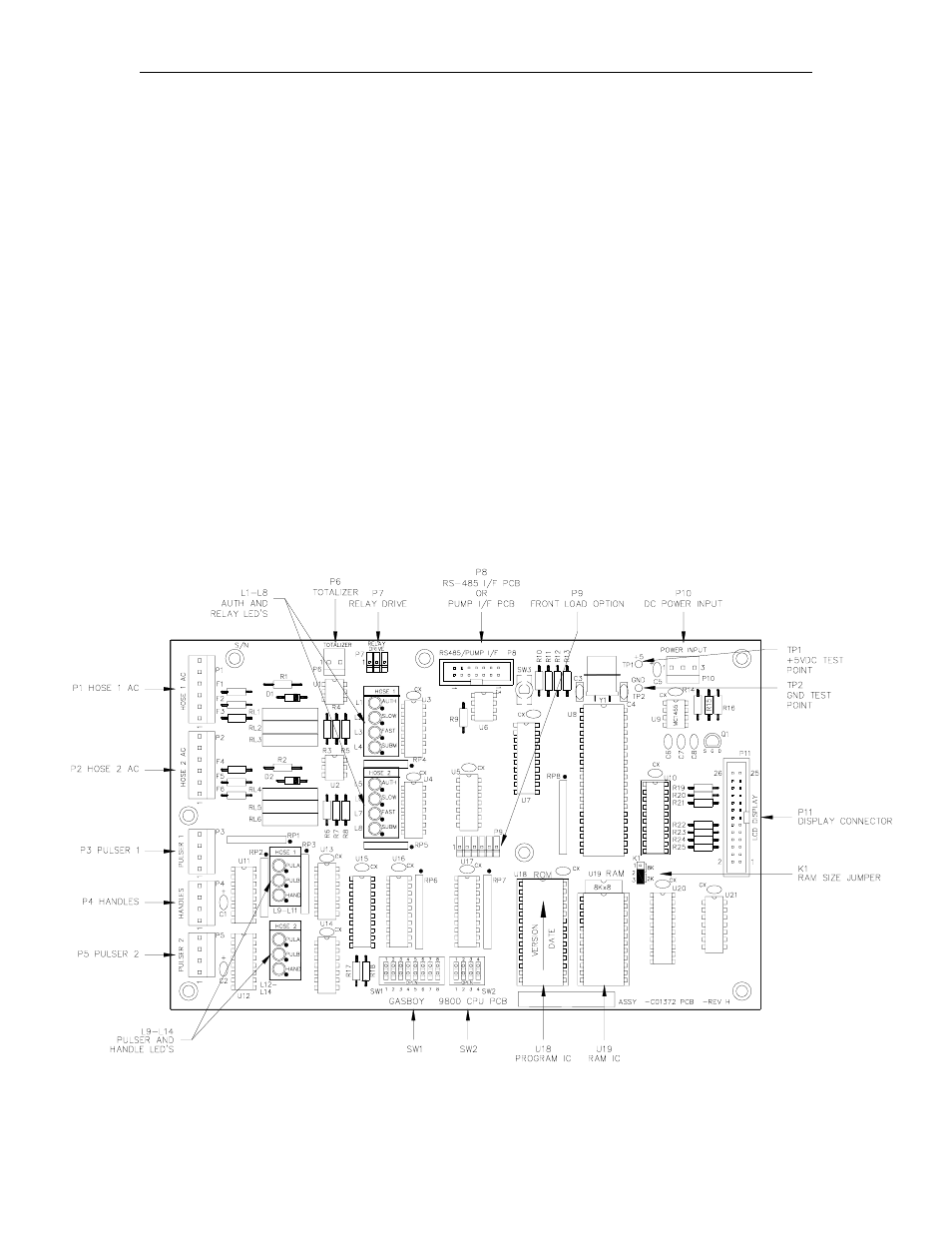
CPU PCB
Single Pump 115VAC (C06391), Twin Pump 115VAC (C06392)
Single Dispenser 115VAC (C06393), Twin Dispenser 115VAC (C06394)
Single Pump 230VAC (C06500), Twin Pump 230VAC (C06501)
Single Dispenser 230VAC (C06502), Twin Dispenser 230VAC (C06503)
The CPU PCB is the heart of the GASBOY Series 9800Q. This CPU PCB:
•
processes and stores all 9800Q data
•
contains a battery-backed RAM IC for transaction and totalizer data retention during power
failures
•
controls the data sent to the display PCB’s
•
controls the relays for each pump side
•
monitors the dual-channel pulser inputs for each pump side
•
monitors the handle switch for each pump side
•
monitors the electronic totalizer switch
•
sends pulser data to an external control system via an optional pump interface PCB
•
communicates on the GASBOY RS-485 pump loop via an optional RS-485 pump interface
PCB
•
allows the user to configure the 9800 through dip switches
•
provides diagnostic LED’s to monitor operation of the unit
Version shown is C06394