Chapter 2 installation instructions – Foxconn 865A05-G-6ELS User Manual
Page 27
21
Chapter 2 Installation Instructions
865A05 G/P/PE/GV User Manual
Jumpers
The users can change the jumper settings on this motherboard if needed. This
section explains how to use the various functions of this motherboard by chang-
ing the jumper settings. Users should read the following contents carefully prior
to modifying any jumper settings.
Description of Jumpers
1. For the jumpers on this motherboard, pin 1 can be identified by the silk-screen printed
“ ” next to it. However, in this manual, pin 1 is simply labeled as “1”.
2. The following table provides some explanation of the jumper pin settings. User
should refer to this when adjusting jumper settings.
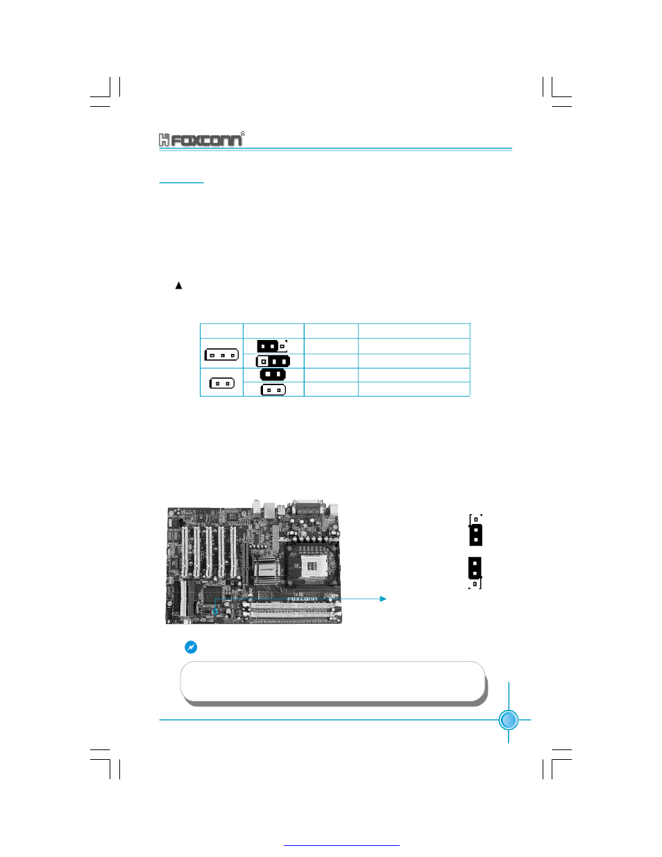
Clear CMOS Jumper: JP1
This motherboard uses the CMOS RAM to store all the set parameters. The
CMOS can be cleared by removing the CMOS jumper. First, turn off the AC power
supply and quickly connect pins 1 and 2 together using the jumper cap. Then,
return the jumper setting to normal (pins 2 and 3 locked together with the jumper
cap), and turn the AC power supply back on.
Jumper Diagram Definition Description
1-2
Set pin 1 and pin 2 closed
2-3
Set pin 2 and pin 3 closed
Closed
Set the pin closed
Open
Set the pin opened
1
1
1
1
1
1
Warning:
1.Disconnect the power cable before adjusting the jumper settings.
2.Do not clear the CMOS while the system is turned on.
Normal status
(default)
1
2
3
Clear CMOS
JP1
1
2
3
PDF created with pdfFactory Pro trial version