Flowserve 3400IQ Digital Positioner User Manual
Page 56
Logix 3400IQ Digital Positioner FCD LGENIM3401-00 – 06/06
6
c
WARNING: Observe precautions for handling electrostatically sensitive devices.
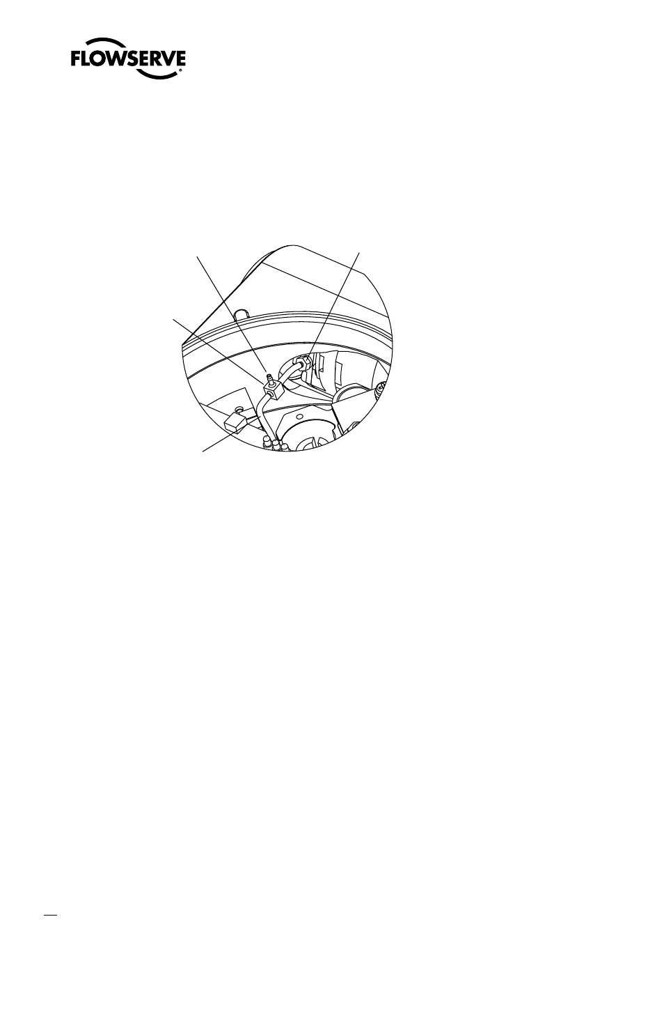
Figure 17: Driver Module Regulator Pressure Check
3FHVMBUPS1SFTTVSF
5FTU1PSU
#BSCFE5FF
$MJQQBSE.JOJNBUJD
1BSU/P5
'MFYJCMF5VCF
GSPN3FHVMBUPS
%SJWFS.PEVMF
#BSCFE'JUUJOH
Y
c
1. Make sure the valve is bypassed or in a safe condition.
2. Remove the main cover.
3. Remove the plastic board cover by removing the three retaining screws.
4. Remove the
1
⁄
16
" flexible tubing from the barbed fitting on the side of the driver module.
5. Obtain a barbed tee and two pieces of
1
⁄
16
" flexible tubing, a few inches in length each.
6. Position the barbed tee between the internal regulator and the driver module by connecting
the
1
⁄
16
" flexible tubing, found in the positioner, to one side of the barbed tee. Using one of the
new flexible tubing pieces, connect the barbed tee to the barbed fitting on the side of the driver
module. Connect the remaining port on the barbed tee to a 0 to 30 psi pressure gauge.
7. Reconnect the air supply to the positioner and read the internal regulator pressure on the 0 to 30
psig gauge. The internal pressure should be set to 17.4 ±0.2 psig. If adjustment is needed, loosen
the set screw retaining nut on the top of the regulator using the
3
⁄
8
" open-end wrench. Then
adjust the regulator pressure by turning the set screw on the top of the regulator with the
3
⁄
32
"
Allen wrench.
8. Once the regulator pressure is set, tighten the set screw retaining nut on the top of the regulator,
remove the air supply to the positioner, remove the barbed tee, and reconnect the flexible tubing
from the regulator to the barbed fitting on the side of the driver module.