7startup, 2 initial dip switch settings – Flowserve 3400IQ Digital Positioner User Manual
Page 22
Logix 3400IQ Digital Positioner FCD LGENIM3401-00 – 06/06
7
Startup
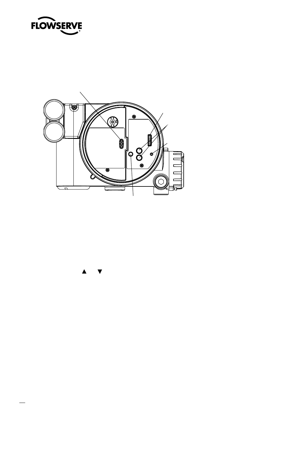
Figure 8: Local User Interface
LEDs
DIP Switch Block
Jog Buttons
Rotary
Selector
Switch
RE-CAL Button
7.1
Logix 3400IQ Local Interface Operation
The Logix 3400IQ local user interface (Figure 8) allows the user to configure the basic operation of
the positioner, tune the response, and calibrate the positioner without additional tools or configura-
tors. The local interface consists of a RE-CAL button for automatic zero and span setting, along
with two jog buttons ( and ) for spanning valve/actuators with no fixed internal stop in the open
position. There is also a DIP switch block containing eight switches. Six of the switches are for basic
configuration settings and two are for FF options. There is also a rotary selector switch for adjusting
the positioner gain settings. For indication of the operational status or alarm conditions there are
three LEDs on the local user interface.
7.2
Initial DIP Switch Settings
Before placing the unit in service, set the DIP switches in the Configuration boxes to the desired
control options. A detailed description of each DIP switch setting follows.
NOTE: The Logix 3400IQ positioner reads the DIP switch settings each time the RE-CAL button is
pressed. If a FF handheld or Host software is used to configure and then calibrate the positioner, the
DIP switches are not read. The auto-tune adjustment switch labeled “GAIN” is always live and can be
adjusted at any time.
Transducer block settings will always override the DIP switch settings until the RE-CAL button is
pressed.