10 stroke length – Flowserve 3400IQ Digital Positioner User Manual
Page 37
3
Logix 3400IQ Digital Positioner FCD LGENIM3401-00 – 06/06
flowserve.com
7.14.10 Stroke Length
Stroke length is used by the travel accumulator. When the stroke length and units are set, the length
is used to determine the total travel accumulated. The travel accumulator will have the units associ-
ated with stroke.
ExAMPLE: Stroke length is set to four inches. If the valve is moved from 0 percent to 100 percent,
four inches will be added to the travel accumulator. The travel accumulator units will be inches. If
Stroke length is 90 degrees for a rotary, the travel accumulator will now have units of degree. A 0
percent to 100 percent stroke will add 90 to the travel accumulator.
NOTE: Stroke length is for information only and is not used during calibration.
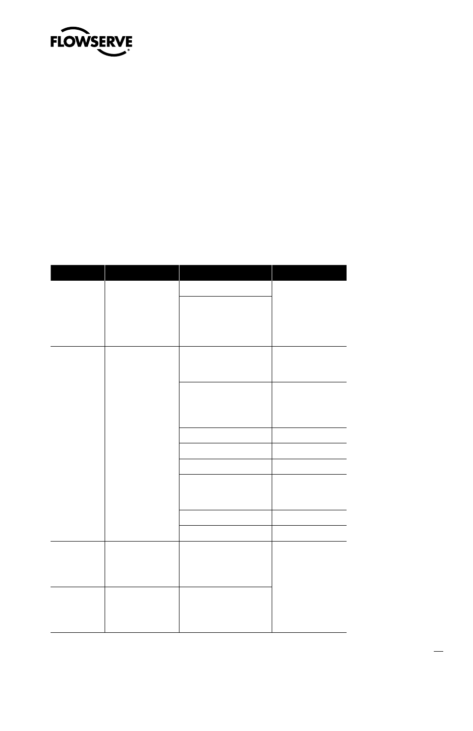
Table IX: Transducer Block Characterization Parameters
Parameter
Description
Value - Meaning
Comments
MODE_BLK
The operating mode
of the transducer
block
Auto - Auto (target mode) The transducer
block must be out
of service before
characterization
can be edited or
changed
OOS - Out of Service
CONTROL_
FLAGS
Byte values which
select positioner
operation features
1 - Quick Opening Curve* Loads factory-
defined QO curve as
custom curve.
2 - Equal Percent Curve*
Loads factory-
defined equal
percent curve as
custom curve.
3 - Actuator Type
4 - Advanced Model
5 - Rotary Actuator Gain
6 - Custom
Characterization Active
Activates custom
curve. If Off,
response is Linear.
7 - Fail Position TBD
8 - Air Action
CURVEX
Numeric X value
array for custom
point. (1 x 21 array
points)
X-axis value for custom
stroke characterization
point. Range –10 to 110
Pair each X-value
with corresponding
Y-value to define
the desired point.
Values must be
in ascending (or
equal) order.
CURVEY
Numeric Y value
array for custom
point. (1 x 21 array
points)
Y-axis value for custom
stroke characterization
point. Range –10 to 110
*NOTE: Must not be selected if a custom curve is to be created or edited.