10 version number checking – Flowserve 3400IQ Digital Positioner User Manual
Page 30
Logix 3400IQ Digital Positioner FCD LGENIM3401-00 – 06/06
30
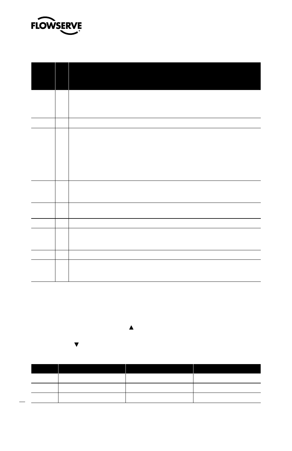
Table VII: Status and Conditions (continued)
Co
lo
rs
Id
en
tifi
er
Indication and Resolution
RGYR
26
Loss of supply pressure The Positioner has determined that the supply pressure is below
15 psi. Check the supply pressure and if OK check the pressure sensor board connections
and replace pressure sensor board if necessary. Minimum recommended supply pressure is
30 psi for proper operation.
RYGG
Factory reset condition Recalibrate.
RYYY
27
Pilot relay non-motion alert Check to make sure the air supply is connected. Also check
the internal wiring harnesses for good connections. This error may be cleared by briefly
pushing the RE-CAL button, which will force the positioner to use the parameters from the
last good calibration. If the positioner still does not operate replace the pneumatic relay
assembly.
RRGG
30
Watchdog timer timeout (also listed as internal voltage reference) This is often caused
when intermittent operation occurs when connecting power. Remove power and then recon-
nect to clear. If problem persists it is a bad electronic assembly, replace.
RRYG
31
Internal temperature alert The internal positioner temperature is currently exceeding
operational limits of -40ºF (-40ºC) or 185ºF (85ºC).
RRYY
32
Piezo voltage error Bad electronic assembly, replace.
RRYR
33
Internal voltage reference error Indicates that the circuit board is drawing too much
power. Check internal wiring and connectors for electrical shorts—if no shorts are present,
replace the electronic assembly.
RRRG
Loss of Inter-PCB Communications Cycle power to restart.
RRRY
34
NV RAM checksum error The checksum of the internal data was not updated correctly.
Cycle power and complete a RE-CAL if error persists. Check internal data to verify correct
settings. If the error still occurs, replace the electronic assembly.
7.10 Version Number Checking
The version number of the embedded code may be checked at any time except during a calibration
by holding down the up arrow Jog button ( ). This will not alter the operation of the unit other than
to change the blink sequence to three blinks indicating the major version number. Holding the down
arrow Jog button ( ) will give the minor version number without affecting operation. The version
codes are interpreted by adding up the numbers assigned according to the following table:
Color
First blink value
Second blink value
Third blink value
Green
0
0
0
Yellow
9
3
1
Red
18
6
2