Flowserve 3400IQ Digital Positioner User Manual
Page 53
3
Logix 3400IQ Digital Positioner FCD LGENIM3401-00 – 06/06
flowserve.com
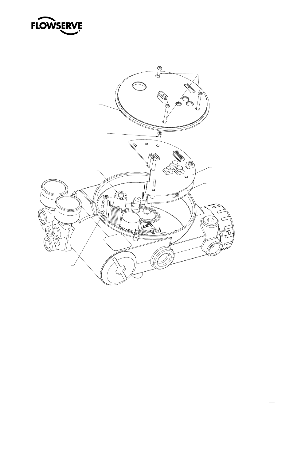
Figure 16: Main PCB Assembly
Plastic Board Cover
Main PCB Retaining Screw
Regulator
Pressure Sensor Board
Main PCB Assembly
Fieldbus PCB
Plastic Cover
Retaining Screws
15. Remove the barbed fitting from the side of the new driver module using the 1/4" nutdriver.
16. Verify that the O-ring is in place on the top of the new driver module. Lay the wires back along
the side of the driver module as shown in Figure 12 and hold the wires in position by hand.
17. Gently insert the driver module into the driver module compartment in the housing. Turn the
driver module clockwise to thread it into the housing. Continue rotating the driver module until
it bottoms out.
18. Once the driver module has bottomed out so that the threads are fully engaged, rotate the driver
module counter clockwise until the flat on the driver module and the flat on the housing are
aligned. This will align the screw hole for the next step.
19. Verify that the nylon gasket is in the counter bore in the driver module retaining screw hole as
shown in Figure 14.