Installation – DNF Controls GTP-32 User Manual
Page 4
- 4 -
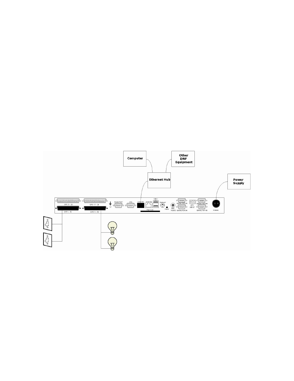
INSTALLATION
CAUTION
Do NOT apply AC voltage to power supply, then connect power supply to GTP-
32. Component damage may occur.
1)
Wire external GPI and external GPO connections to supplied D37 male
connectors, per the GPIO connector wiring diagram in
SPECIFICATIONS section.
2)
Connect wired D37 connectors from step 1 to GTP-32 connector
labeled “GPI 1-16”, “GPI 17-32”, “GPO 1-16”, or “GPO 17-32”.
3)
Connect Cat 5 cable to GTP-32 connector labeled “E-NET #1”.
Connect other end of Cat 5 cable to customer supplied ethernet hub.
4)
Connect power supply’s round locking female connector to GTP-32
connector labeled “POWER“.
5)
Connect female side of power cable to supplied power supply.
6)
Connect male side of power cable to AC voltage, 100 – 240.
7)
Push GTP-32 power switch, located on front panel, to ON position. “O”
on power switch is OFF position.
8)
Front panel LEDs will flash during power up. When power up and
system initialization completes, the front panel LEDs will turn off and
the front panel display will show Model Number and Software Version.
Allow 25 seconds for power up and system initialization to complete.
No connection is required for the REF VIDEO, DIAGNOSTIC, or VGA
connectors on the rear of the GTP-32. LTC and Serial Port connectors may be
required depending on Protocols and Options.