Pushbutton connection, Wired photocell connection – Daktronics 2000 Rodeo OmniSport User Manual
Page 21
Timing System Setup
13
Pushbutton Connection
Connect up to 3 pushbuttons (part # 0A-1056-0156)
for use in Timed Events to the TIMER 1, TIMER 2,
and TIMER 3 jacks on the front of the Rodeo
Timing Interface. The TIMER 1 input may also be
used to start and stop the clock in Scored Events.
Note: Pay attention to the orientation of the
GND tab of the banana plug – this must
connect into the black jack (Figure 19).
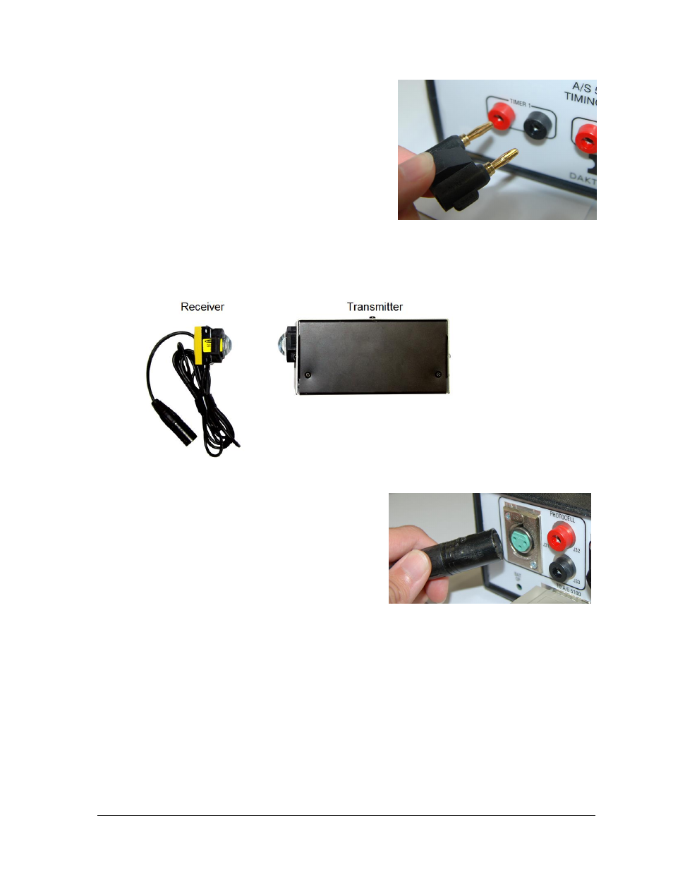
Wired Photocell Connection
Wired photocells may be used for automatic timing of timed events. The system consists of a
transmitter (part # 0A-1163-0025) and a receiver (part # 0A-1163-0024). Refer to Figure 20.
Connect the receiver to the J31 PHOTOCELL
XLR jack on the rear of the Rodeo Timing
Interface (Figure 21).
Note: J32 / J33 is an optional photocell input.
This 2-pin connector does not provide power,
so the photocell receiver would require an
alternate power supply.
The transmitter is housed in an enclosure with two 6 VDC batteries (part # BT-1019). A 12
VDC wall plug-in charger (part # 0A-1088-0013) is included to provide power and charge the
batteries. Use the rocker switch on the rear of the unit to power it on (|) and off (O). The
transmitter is designed to operate 75 hours on a full charge. Note that it can take up to 6
hours to fully recharge the battery.
Ensure the photocell eyes are aligned and level, with a clear line of sight between them.
Both transmitter and receiver feature mounting holes for included tripods (part # A-1509).
CAUTION!
DANGER OF EXPLOSION IF BATTERY IS INCORRECTLY REPLACED.
REPLACE ONLY WITH THE SAME OR EQUIVALENT TYPE.
WARNNING!
Do not expose batteries to excessive heat, such as direct sunlight or open fire.
Figure 19: Pushbutton Connection
Figure 20: Wired Photocell System
Figure 21: Photocell Receiver Connection