Section 2: timing system setup, 1 connections on the console, Section 2 – Daktronics 2000 Rodeo OmniSport User Manual
Page 15: Timing system setup, Connections on the console
Timing System Setup
7
Section 2:
Timing System Setup
2.1 Connections on the Console
Reference Drawing:
Connector Designations: OmniSport 2000 ............................................. Drawing A-154282
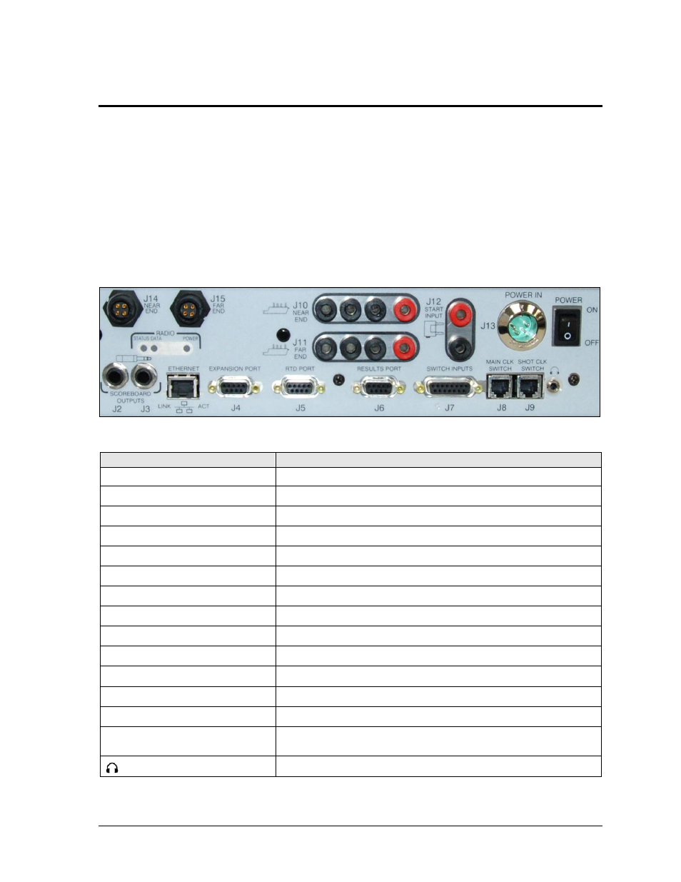
It is important to become familiar with the connections on the back of the OmniSport 2000
timing console to ensure all equipment is properly connected before each event. Refer to
Figure 2 and Drawing A-154282. Make ALL connections to the OmniSport 2000 console and
attached equipment BEFORE turning on the console’s power switch.
Connection
Function
J2 / J3
– SCOREBOARD OUTPUTS Control numeric rodeo scoreboards/timers
J4
– EXPANSION PORT
Communication with FarmTek wireless photocells
J5
– RTD PORT
Bi-directional communication with Daktronics display control software
J6
– RESULTS PORT
Bi-directional communication with DakStats Rodeo software
J7
– SWITCH INPUTS
Communication with rodeo interface (wired photocells, push buttons)
J8
– MAIN CLK SWITCH
(Not used for rodeo applications)
J9
– SHOT CLK SWITCH
Start/Stop/Reset clock in Scored Events mode
J10
– NEAR END
(Not used for rodeo applications)
J11
– FAR END
(Not used for rodeo applications)
J12
– START INPUT
(Not used for rodeo applications)
J13
– POWER IN
Supplies power from wallpack transformer
J14
– NEAR END
Communication with wireless judge
s’ consoles
J15
– FAR END
(Not used for rodeo applications)
ETHERNET
Bi-directional communication with DakStats Rodeo software and
Daktronics matrix display control software
Hear the console beeper via headphones
Figure 2: OmniSport 2000 Console Rear View