Comtest Networks MTAS-192 METALLIC TEST ACCESS SYSTEM User Manual
Page 54
Comtest Networks
CT-IG-MTAS192-2008-v1_8.doc
MTAS-192
48
Installation Guide
May 2008
Serial Cabling
To communicate with the MTAS serially, use the AUX 1 RJ-45 jack located on the
Master (MTAS-CM) control card's front panel. Configure the terminal emulation
software for 9600 baud, with 8 data bits, 2 stop bits, no parity and no flow control. If the
connection is good, you should see a TL1>> prompt.
The pin layout for the RJ-45 serial port (AUX 1) follows the RS-232D standard.
Table 20: Pin Layout for RJ-45 (AUX 1) Serial Port using RS-232D Standard
Pin No.
Name
Notes/Description
1
DSR/RI
Data Set Ready/Ring Indicator
2
DCD
Data Carrier Detect
3
DTR
Data Terminal Ready
4 SGND
Signal
Ground
5 RD
Receive
Data
6 TD
Transmit
Data
7
CTS
Clear to Send
8
RTS
Request to Send
NOTE: Only pins 4 (GND), 5 (RD), and 6 (TD) are used for this release.
Table 21: Pin Layout for Serial RJ-45
→ DB-9 Adapter
RJ-45-F to DB-9-F Serial Adapter pinout
MTAS Aux 1
pinout
RJ-45 Female
Colour
DB-9 Female
4
→ SGND
4 Red
5
5
→ RD
5 Yellow
2
6
→ TD
6 Green
3
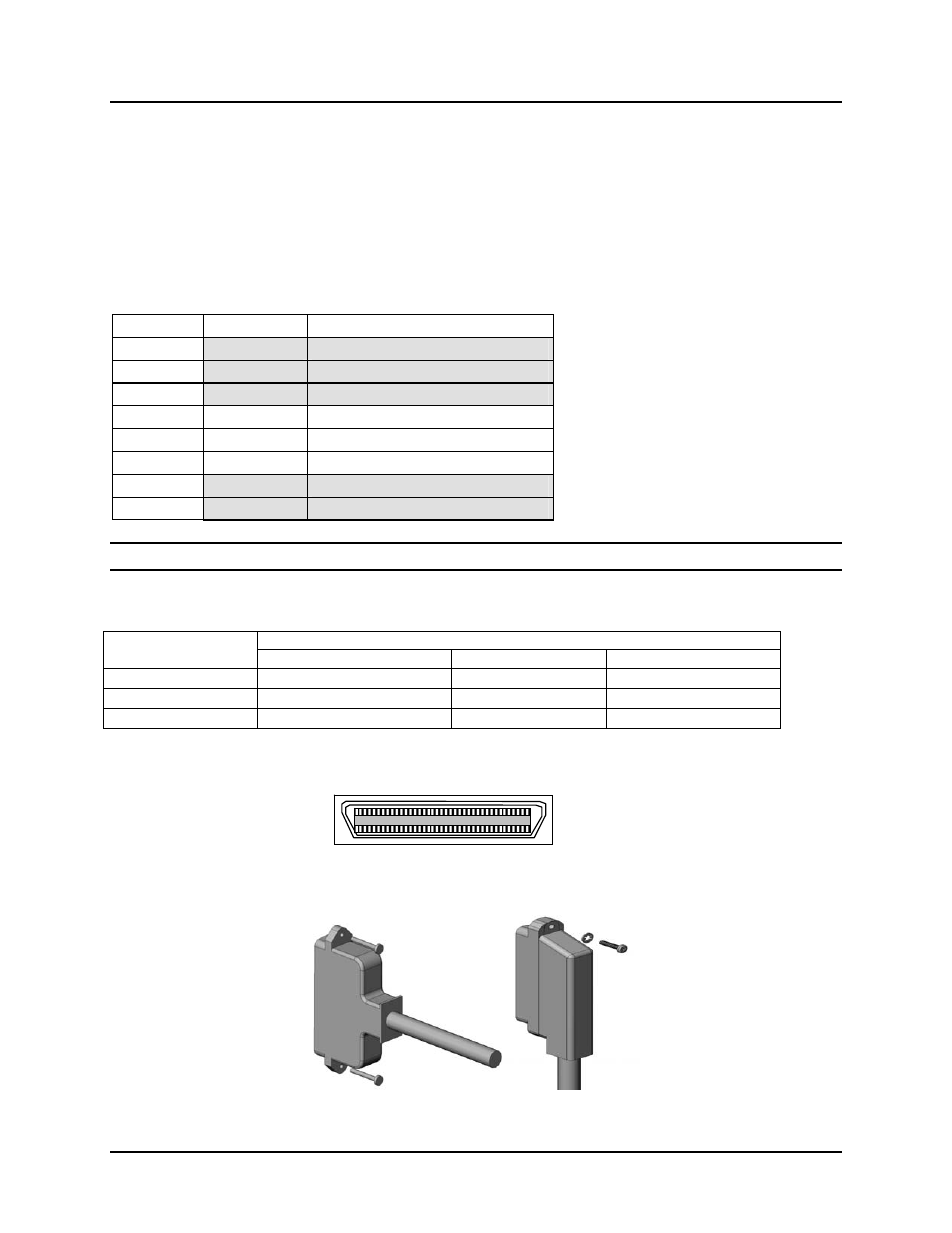
RJ-21 Cabling
Figure 39: RJ-21 Pinout Diagram
Figure 40: D-type and Right Angle (90 Degree) RJ-21 Connectors
Pin 1
Pin 26