Comtest Networks MTAS-192 METALLIC TEST ACCESS SYSTEM User Manual
Page 49
CT-IG-MTAS192-2008-v1_8.doc
Comtest Networks
MTAS-192
June 2006
Installation Guide
43
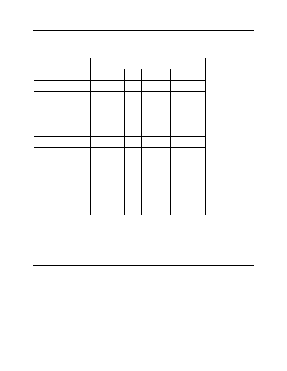
MTAS Control Card Shelf Address DIP Switch Settings
Table 15: MTAS Control Card Shelf Address DIP Switch Settings
Physical Setting
Binary ID
MTAS
Shelf
#1 #2 #3 #4 8
4
2
1
MTAS-CM
master
Down
Down
Down
Down
0 0 0 0
MTAS-CS slave #1
Down Down
Down
Up
0
0
0
1
MTAS-CS slave #2
Down Down
Up
Down
0
0
1
0
MTAS-CS slave #3
Down Down
Up
Up
0
0
1
1
MTAS-CS slave #4
Down
Up
Down
Down
0
1
0
0
MTAS-CS slave #5
Down
Up
Down
Up
0
1
0
1
MTAS-CS slave #6
Down
Up
Up
Down
0
1
1
0
MTAS-CS slave #7
Down
Up
Up
Up
0
1
1
1
MTAS-CS slave #8
Up
Down
Down
Down
1
0
0
0
MTAS-CS slave #9
Up
Down
Down
Up
1
0
0
1
MTAS-CS slave #10
Up
Down
Up
Down
1
0
1
0
MTAS-CS slave #11
Up
Down
Up
Up
1
0
1
1
The DIP switch settings may be verified by physical inspection or by viewing the slave
card faceplate Binary ID LEDs.
If DIP switch settings are duplicated in the daisy chain, between master and slave, or
between two slaves, these cards will go into alarm.
NOTE: For DIP switch settings, a logical 0 is represented by having the DIP switch in
the DOWN position. A logical 1 is represented by having the DIP switch in the UP
position. Please refer to Figure 18: MTAS-CM (Control Master) DIP Switch Location
and Figure 19: MTAS-CS (Control Slave) DIP Switch Location.