Chapter 5 activation and testing – Comtest Networks MTAS-192 METALLIC TEST ACCESS SYSTEM User Manual
Page 39
CT-IG-MTAS192-2008-v1_8.doc
Comtest Networks
MTAS-192
June 2006
Installation Guide
33
Chapter 5
Activation and Testing
5.1 Introduction
This chapter describes how to power up the MTAS-192 shelf and verify that it is
operating correctly, after all required physical installation of the MTAS shelf, circuit
packs, and associated cabling has been completed as described in the preceding
chapters.
5.2 Powering
the
MTAS-192
Apply power to the MTAS shelf by inserting the fuse corresponding to the MTAS shelf at
the Power Distribution Block at the top of the rack. (See Appendix A MTAS
Specifications for fuse requirements). For redundant power, remember to insert the
corresponding A and B feed fuses.
5.3
Validating Operation of Control Cards and Line Cards
After applying power to the MTAS-192 shelf, the Light Emitting Diodes (LEDs) on the
card faceplates should behave as listed in Table 12. Figure 33 and Figure 34 show
flowcharts for validating operation of these cards.
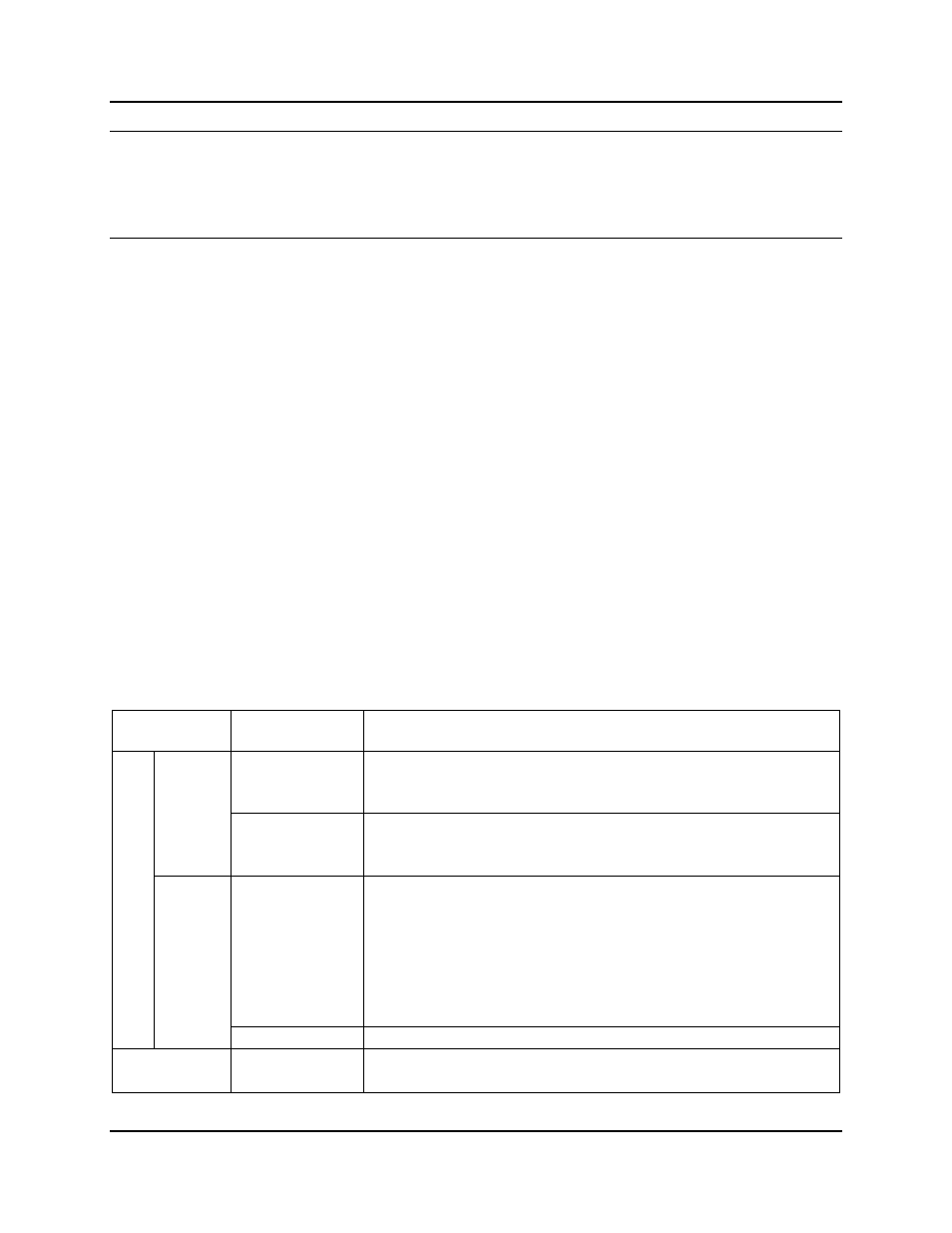
Table 12: LED Operation after Successful Power Up
Cards
LEDs
LED Action After Power Up
PWR/Status
Immediately light solid red, then after a few seconds
light solid green.
Master
Shelf
TAPs 1 and 2
Immediately light solid red, then after a few seconds
light solid green.
PWR/Status
Immediately flash red for several seconds, then light
solid amber. This LED will remain amber until it is
discovered by the master shelf (typically 30 seconds),
at which time it will light solid green and each line card
will be then be restarted, processing from left to right,
with its PWR/Status LED lighting – flashing amber for a
few seconds, then solid green.
Control Car
d
s
Slave
Shelf
Binary ID
Indicates configured chassis ID.
Line Cards
PWR/Status
Flicker amber until the card can read a valid chassis ID,
then light solid green.