Comtech EF Data DD2401 VME User Manual
Page 73
DD2401 VME L-Band Demodulator Card Installation & Operational Manual
Rear Panel Interfaces
MN-VME2401 – Rev. B
5-5
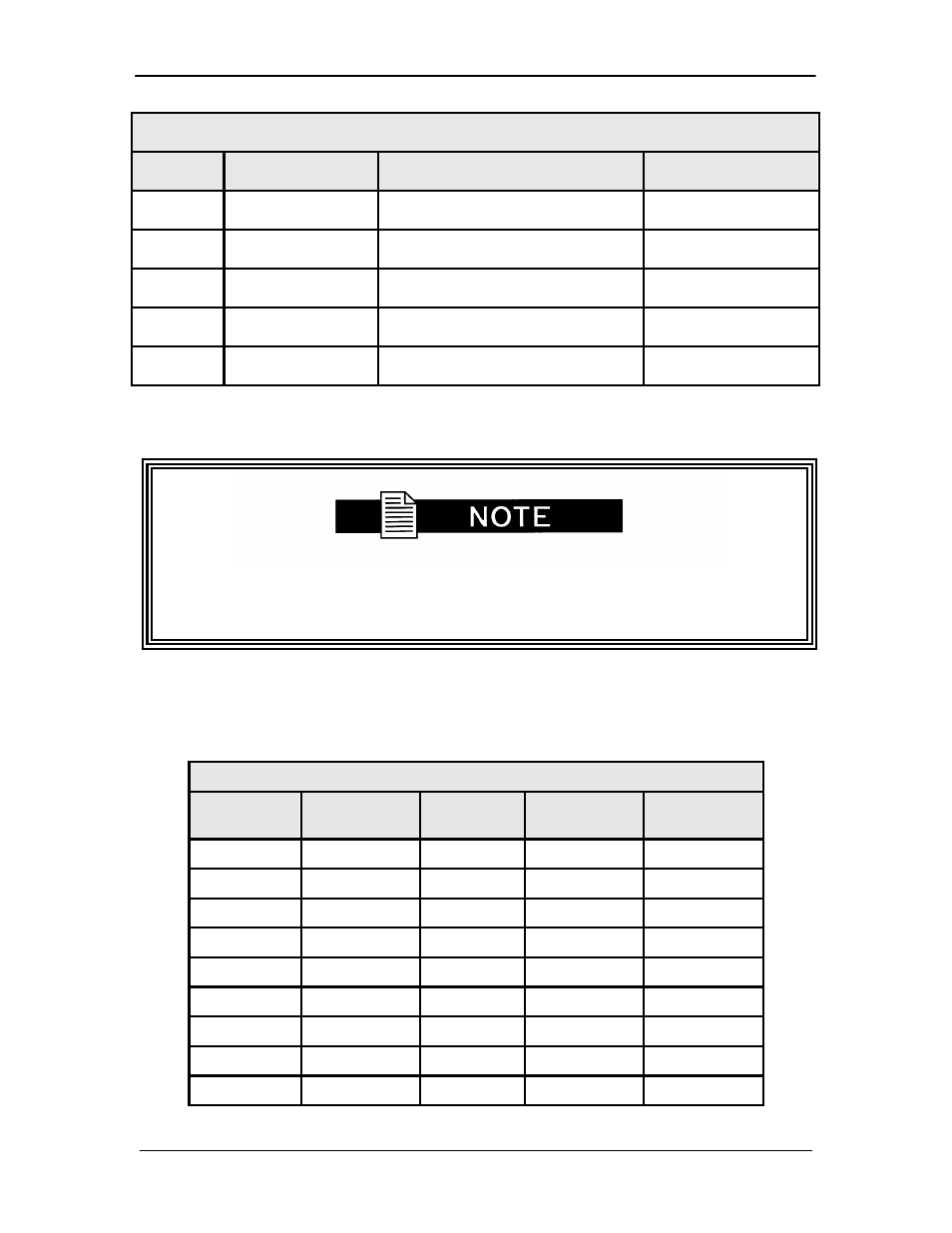
Table 5-5. RS-485 Remote Port – 9-Pin Female D-Sub Connector (J5)
Pin #
Signal
Description
Direction
1
TX-485B
Transmit Data RS-485 (+)
Output
5
GND
Ground
---
6
TX-485A
Transmit Data RS-485 (-)
Output
8
RX-485B
Receive Data RS-485 (+)
Input
9
RX-485A
Receive Data RS-485 (-)
Input
The user must set demodulator addresses prior to connecting to remote port. Refer to
Section 5.7, “Remote Addresses”.
5.7 Remote Addresses
The demodulator supports up to 16 different remote addresses. Refer to Tables 5-6 and 5-7 for
S1 DIP Switch settings. The S1 DIP switch is located on the main board.
Table 5-6. S1 DIP Switch
Position
1
Position
2
Position
3
Position
4
Address in
Decimal
off
off
off
off
32 (default)
on
off
off
off
33
off
on
off
off
34
on
on
off
off
35
off
off
on
off
36
on
off
on
off
37
off
on
on
off
38
on
on
on
off
39
off
off
off
on
40
- CDD-880 (124 pages)
- CDM-800 (130 pages)
- ODMR-840 (184 pages)
- CDM-750 (302 pages)
- CDM-840 (244 pages)
- SLM-5650A (420 pages)
- CTOG-250 (236 pages)
- CDM-700 (256 pages)
- CDM-760 (416 pages)
- CDM-710G (246 pages)
- CDM-600/600L (278 pages)
- CDMR-570L (512 pages)
- CDM-625 (684 pages)
- CDM-625A (756 pages)
- CDD-564A (240 pages)
- CDD-564L (254 pages)
- CLO-10 (134 pages)
- MCED-100 (96 pages)
- CDMR-570AL (618 pages)
- CDM-600 LDPC (2 pages)
- BUC Power Supply Ground Cable (2 pages)
- MPP70 Hardware Kit for CDM-570L (4 pages)
- MPP50 Hardware Kit for CDM-570L (4 pages)
- CDM-625 DC-AC Conversion (4 pages)
- CDM-625 DC-AC Conversion with IP Packet Processor (4 pages)
- DMDVR20 LBST Rev 1.1 (117 pages)
- DMD2050E (212 pages)
- DMD-2050 (342 pages)
- DMD1050 (188 pages)
- OM20 (220 pages)
- QAM256 (87 pages)
- DD240XR Rev Е (121 pages)
- MM200 ASI Field (5 pages)
- DM240-DVB (196 pages)
- MM200 (192 pages)
- CRS-150 (78 pages)
- CRS-280L (64 pages)
- CRS-170A (172 pages)
- CRS-180 (136 pages)
- SMS-301 (124 pages)
- CiM-25/8000 (186 pages)
- CiM-25 (26 pages)
- CRS-500 (218 pages)
- CRS-311 (196 pages)
- CIC-20 LVDS to HSSI (26 pages)