Comtech EF Data DD2401 VME User Manual
Page 38
User Interfaces
DD2401 VME L-Band Demodulator Card Installation & Operational Manual
4-14
MN-VME2401 – Rev. B
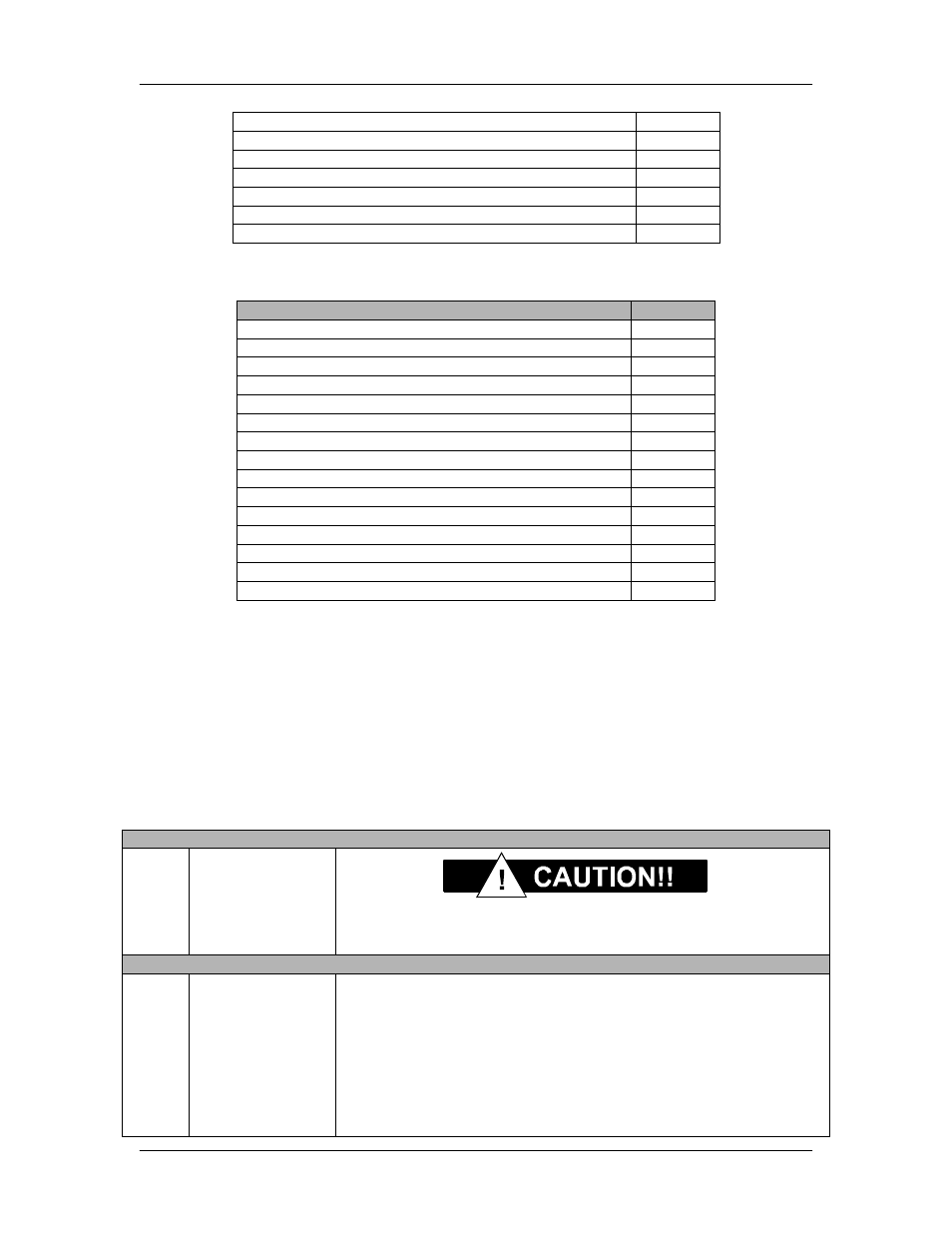
Command Demod Operating Mode
2A17h
Command Demod BER Measure Period
2A1Ah
Command Demod Terrestrial Loopback
2A1Ch
Command Demod Baseband Loopback
2A1Dh
Command Demod Center Buffer
2A20h
Command Demod Data Invert
2A21h
Command Demod Buffer Size Time/Bytes
2A31h
4.4.11 Module Command Set
RLLP Command
Opcode
Query Module Identification
2403h
Query Module Current Alarms
240Ah
Query Module Time
240Eh
Query Module Date
240Fh
Query Module Time and Date
2410h
Command Module Control Mode
2600h
Command Module Ext Ref Source
2616h
Command Mod Ext Ref Frequency
261Bh
Command Module Clear Latched Alarms
2C03h
Command Module Set Time
2C04h
Command Module Set Date
2C05h
Command Module Set Time and Date
2C06h
Command Module Soft Reset
2C07h
Command Module Eb/No Threshold
2C08h
Command Module Default Configuration
2C30h
1
Applies to base band frequency modems only.
2
Applies to LB/ST modem configurations only.
4.4.12
Detailed Command Descriptions
4.4.12.1
DMD2401 Demodulator
Note: All bytes preceded by a * are not applicable to the DD2401/DD2401L and should be considered
as reserved and there returned values ignored.
Opcode: <2401h>
Query a Demodulator’s Configuration and Status
Query Response
<1>
Number of Nonvol
bytes
See Paragraph B.6. This is the number of configuration bytes
and is an offset to the start of the status block.
Configuration Bytes
<4>
<4>
<1>
<4>
Frequency
Data Rate
Sweep Boundary
External
Reference
Binary Value, 1 Hz Steps
Binary Value, 1 bps Steps
Sweep Limits (Max of
±
42 kHz)
Unsigned Binary Value in Hz