Comtech EF Data DD2401 VME User Manual
Page 59
DD2401 VME L-Band Demodulator Card Installation & Operational Manual
User Interfaces
MN-VME2401 – Rev. B
4-35
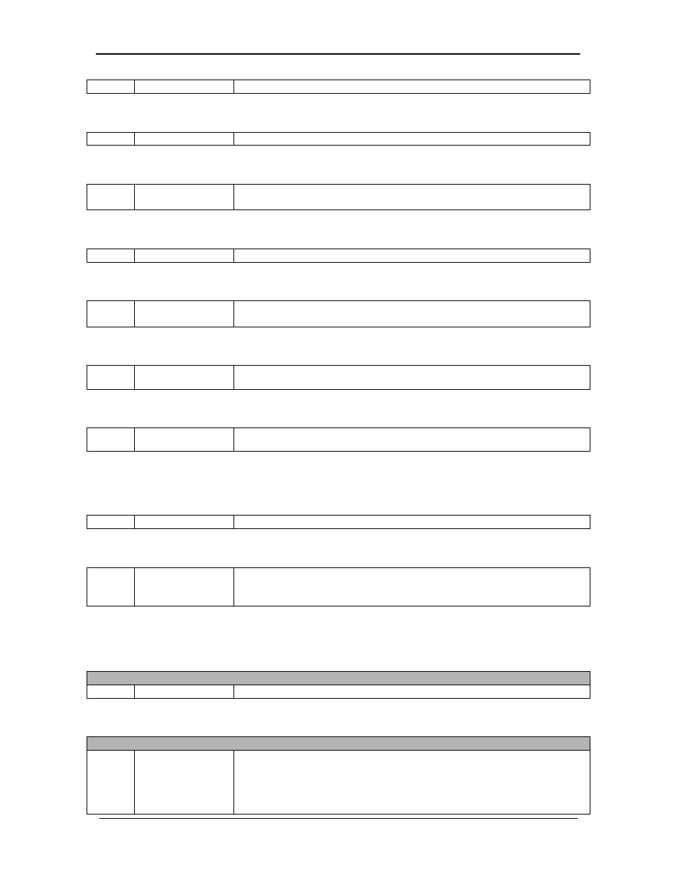
<1>
Spectrum
0 = Normal, 1 = Inverted
Opcode: <2A11h>
Command a Demodulator’s Buffer Clock
<1>
Buffer Clock
0 = External, 1 = Internal, 2 = EXC, 3 = RX SAT
Opcode: <2A12h>
Command a Demodulator’s Buffer Clock Polarity
<1>
Buffer Clock
Polarity
0 = Normal, 1 = Inverted
Opcode: <2A17h>
Command a Demodulator’s Operating Mode
<1>
Operating Mode
0 = Stop, 1 = 2047 Test
Opcode: <2A1Ah>
Command a Demodulator’s BER Exponent
<1>
BER Measure
Period
Number of Bits in Measurement Period in Powers of Ten (ex: 6 = 10
6
Bits)
Opcode: <2A1Ch>
Command a Demodulator’s Terrestrial Loopback
<1>
Rx Terrestrial
Loopback
0 = Disabled, 1 = Enabled
Opcode: <2A1Dh>
Command a Demodulator’s Baseband Loopback
<1>
Rx Baseband
Loopback
0 = Disabled, 1 = Enabled
Opcode: <2A20h>
Command Center Buffer (No Parameters)
Opcode: <2A21h>
Command a Demodulator’s Data Invert
<1>
Data Invert
0 = Normal, 1 = Inverted
Opcode: <2A31h>
Command a Demodulator’s Buffer Size
<4>
Buffer Size
Byte 1 - 2 = buffer size in ms OR Byte 3 - 4 = buffer size in bytes
(Either ms or bytes must be specified - the other field should be
0xFFFF)
4.4.12.2
Module Queries & Commands
Opcode: <2403h>
Query a Module’s Identification
Query response
<1>
Modem ID
DD2401/DD2401L Demodulator = 27
Opcode: <240Eh>
Query Time
Query response
<1>
<1>
<1>
Hour
Minute
Second
0 – 23
0 – 59
0 – 59