2 clocking options, 1 rx buffer clock options, Figure 3-4. clocking and polarity diagram – Comtech EF Data DD2401 VME User Manual
Page 22: Rx satellite clock (recovered from satellite)
Theory of Operation
DD2401 VME L-Band Demodulator Card Installation & Operational Manual
3-4
MN-VME2401 – Rev. B
encoder which adds 2t = (N - K) check bytes to produce an N byte RS Block. The RS Decoder
can then correct up to “t” erred bytes in the block (refer to Figure 3-4 and Table 3-1).
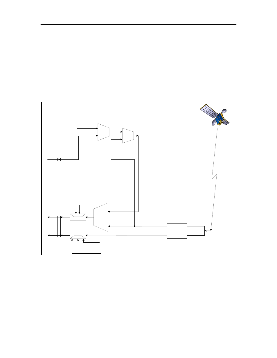
3.2 Clocking Options
The Demodulator supports a number of different clocking options that can be recovered
from the satellite or the terrestrial links. The various clocking options allow users to
determine which clock will best fit their applications. Figure 3-7 gives an overview on
how the modem processes the various clocks for the Rx Buffer Clock source.
EXT REF
EXTERNAL
INTERNAL
SCT CLK
REF FREQ
SRC
RECEIVE
CLOCK & DATA
RECOVERY
SCT
RX SAT
RT
RD
BUFFER CLK
SRC
DEMODULATION
J19
J10
DATA POLARITY
BUFFER CLK POL
NORMAL
INVERTED
INVERT NONE
INV. BASEBAND
INV. TERR DATA
Figure 3-4. Clocking and Polarity Diagram
3.2.1 RX Buffer Clock Options
The modem supports a number of RX Buffer clock options that can be recovered from the
satellite, terrestrial links, internally or externally. The various clocking options allow users to
determine which clock will best fit their applications. Figure 3-7 gives an overview on how the
modem processes the various clocks for the Tx Clock and the Rx Buffer Clock. The modem
allows users to select clock polarity and Rx Clocks may be independently locked. The following
RX Buffer clock selections are available:
Rx Satellite Clock (Recovered from Satellite)