1 theory of operation – Comtech EF Data SDM-100A User Manual
Page 139
SDM-100A Satellite Modem
Theory of Operation
Rev. 0
4–23
SD
BA
DA
TT
5
P5
TT
RS
CA
(TT)
DA
J1
24
2
4
9
(RS)
(SD)
CA
BA
-MC
-MC
MC
DF
DF
SD
RS
MC
6
7
13
15
16
10
8
ST
RT
DF
MF
MF
RT
DD
MF
(RT)
(ST)
DD
DB
MOD FAULT
DEMOD FAULT
11
25
17
15
6
5
3
(DM)
(CS)
(RD)
CC
CB
BB
DB
ST
DM
RD
CS
9
14
11
12
30
33,34
RR
+12V
-CP
DM
CS
CB
CC
(RR)
CF
GND
CP
8
18
1,7
CF
BB
RD
RR
GND
INF1
-12V
+5V
35,36
37,38
4
1,2
3
39,40
INF0
GND
CP
-
CP
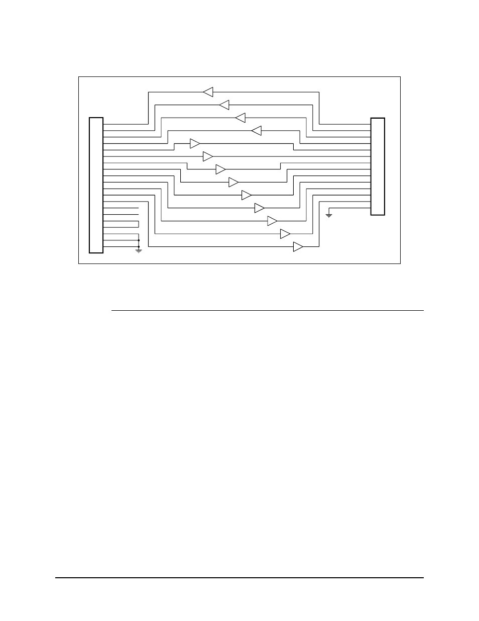
Figure 4-8. RS-232-C Interface
4.4.3.1 Theory of Operation
The RS-232-C interface provides a Send Timing (ST) clock signal at the modem data
rate. This signal may be set to NORMAL or INVERT at jumper P3 on the Interface
board.
• In the INTERNAL clock mode, the data to be transmitted, Send Data (SD), must
be synchronized to ST.
• In the EXTERNAL clock mode, the clock is accepted on the Terminal Timing
(TT) input to clock-in the data to be transmitted.
In either case, the phase relationship between the clock and data is not important as long
as it meets the jitter specifications of RS-422/449. This is because a clock phase
correction circuit is provided, which shifts the clock away from the data transition times.