Table 2-2, Table 2-3 – Comtech EF Data MiniMac Installation ManualOperation Manual Operation Manual User Manual
Page 111

MINIMAC Rack Management System
Installation
Rev. 0
2–9
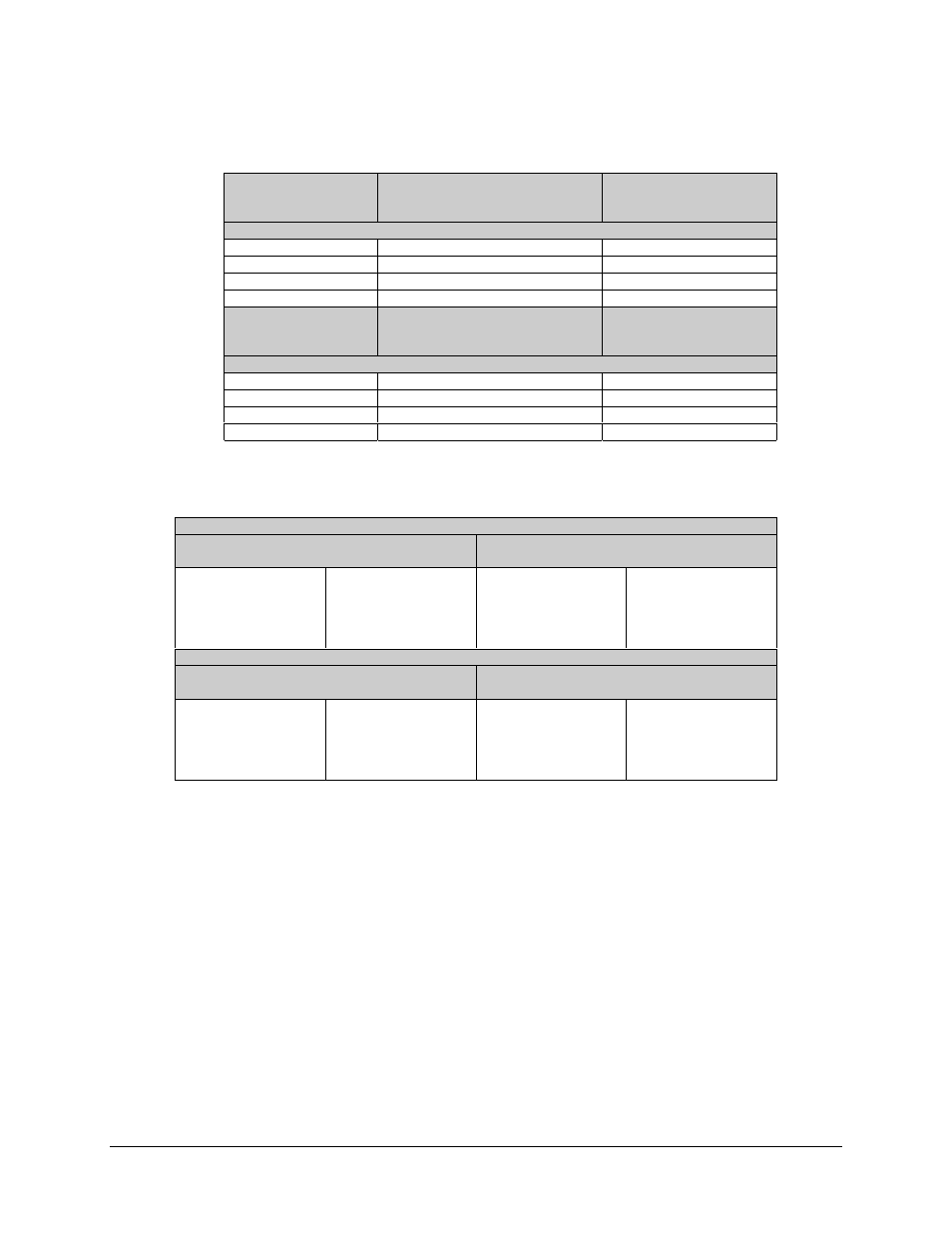
Table 2-2 . Star Gate RS-232 MiniMAC Cables
Star Gate
Cable End
DB25 Male Pin #
Signal Name
(Relative to Star Gate)
Device
Remote
DB9 Male Pin #
RS-232 Connection Diagram MiniMAC to Remote
1
Shield
2
TX (Output)
3
3
RX (Input)
2
7
Ground
5
Star Gate
Cable End
DB25 Male Pin #
Signal Name
(Relative to Star Gate)
ASYNC
Cable End
DB25 Male Pin #
RS-232 Connection Diagram MiniMAC to ASYNC
1
Shield
2
TX (Output)
3
3
RX (Input)
2
7
Ground
7
Table 2-3. MOXA to Modem (or Switch) Remote Port Cable RS-422 (4-Wire)
MOXA to Modem (or Switch) Remote Port Cable RS-485 (4-Wire)
MOXA Port 1-8
25-Pin ‘D’ Type Male and Hood
Modem (or Switch) Remote Port
9-Pin ‘D’ Type Male and Hood
Pin 3
Pin 16
Pin 2
Pin 14
Pin 7
TXB (+)
TXA (-)
RXB (+)
RXA (-)
GND
Pin 4
Pin 5
Pin 8
Pin 9
Pin 1
TX+
TX-
RX+
RX-
GND
MOXA to Asynchronous Port (ESC) Cable RS-422 (4-Wire)
MOXA Port 1-8
25-Pin ‘D’ Type Male and Hood
ASYNC ESC on Switch or BOP
25-Pin ‘D’ Type Male and Hood
Pin 3
Pin 16
Pin 2
Pin 14
Pin 7
TXB (+)
TXA (-)
RXB (+)
RXA (-)
GND
Pin 14
Pin 2
Pin 16
Pin 3
Pin 7
TX+
TX-
RX+
RX-
GND
