3 utility connector group, 1 ‘redundancy’ connector (future), 2 ‘console’ connector – Comtech EF Data CDD-880 User Manual
Page 43
CDD-880 Multi Receiver Router
Revision 1
Rear Panel Connections
MN-CDD880
3–7
3.2.3
Utility Connector Group
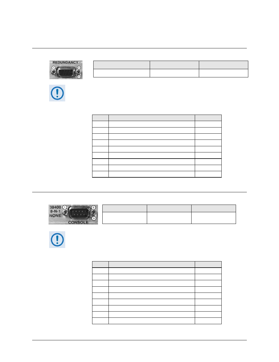
3.2.3.1 ‘REDUNDANCY’ Connector
(FUTURE)
Connector Type
Name
Direction
D-sub 9-pin female
REDUNDANCY In/Out
This interface is intended for future use for connection to an optional CEFD CRS‐170A
1:1 Redundancy Switch for L‐Band operation.
Table 3-1. ‘REDUNDANCY’ Connector Pinout
Pin #
Description
Direction
1 Ground
–
6
Transmit Serial Data – auxiliary channel
Out
2 Receive Serial Data – auxiliary channel
In
7
Redundancy Out 1
Out
3 Redundancy In 1
In
8
Redundancy Out 2
Out
4 Redundancy In 2
In
9
Fused +12 volt
Out
5 Ground
–
3.2.3.2 ‘CONSOLE’ Connector
Connector Type
Name
Direction
D‐sub 9‐pin male
CONSOLE
In/Out
This interface is used for EIA‐232 communications. It is intended for connection to a
user‐provided M&C computer or VT (Video Terminal) device. The standard
configuration settings for the serial interface are provided here.
Table 3-2. ‘CONSOLE’ Connector Pinout
Pin #
Description
Direction
1 Ground –
6
Reserved - do not connect to this pin
–
2 EIA-232 Transmit Data
Out
7
Reserved - do not connect to this pin
–
3 EIA-232 Receive Data
In
8
Reserved - do not connect to this pin
–
4 Reserved - do not connect to this pin
–
9
Reserved - do not connect to this pin
–
5 Ground –