Cdd-880 cabling connections, 2 cdd-880 cabling connections – Comtech EF Data CDD-880 User Manual
Page 41
CDD-880 Multi Receiver Router
Revision 1
Rear Panel Connections
MN-CDD880
3–5
3.2
CDD-880 Cabling Connections
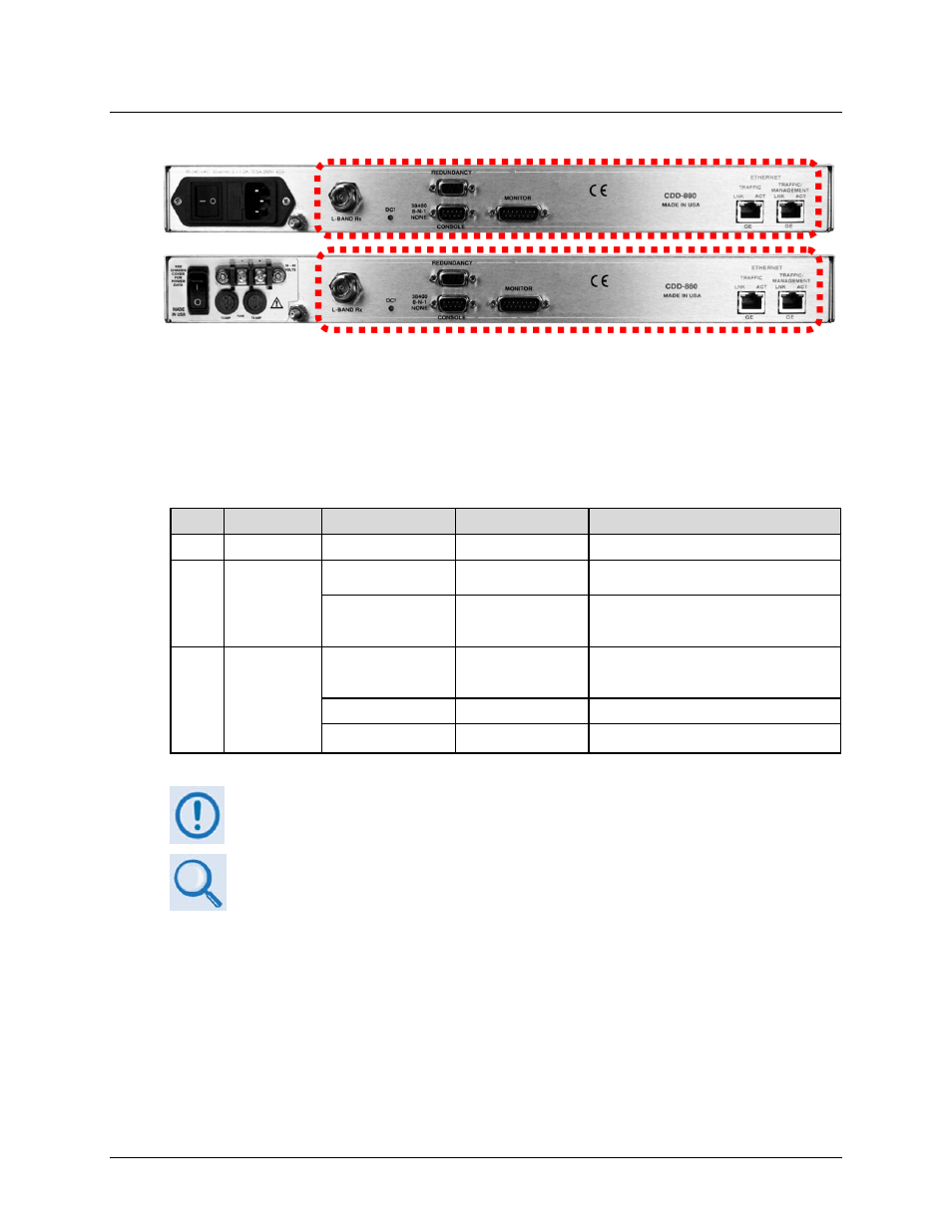
Figure 3‐3. CDD‐880 Cabling Connections
The CDD‐880 rear panel connectors, shown here in Figure 3‐3, provide all necessary external
connections between the unit and other equipment. The table that follows summarizes the
connectors provided here, grouped according to service function:
Sect.
Service Type
Connector Name
Connector Type
Connector Function
3.2.1 IF
L-BAND
Rx
50Ω Type ‘N’ female
L-Band Rx Input
3.2.2
Terrestrial Data
ETHERNET |
TRAFFIC | GE
RJ-45 female
10/100/1000 BaseT Gigabit Ethernet
interface (IEEE 802.3ab)
ETHERNET |
TRAFFIC /
MANAGEMENT | GE
RJ-45 female
10/100/1000 BaseT Gigabit Ethernet
Traffic OR management/data interface
(IEEE 802.ab)
3.2.3 Utility
REDUNDANCY
D-sub 9-pin female
(FUTURE)
For connection to an
optional 1:1 or 1”N CEFD Redundancy
Switch
CONSOLE
D-sub 9-pin male
Serial Remote Interface (EIA-232)
MONITOR
D-sub 15-pin male
I&Q Constellation/Rx AGC Monitor Output
The European EMC Directive (EN55022, EN50082‐1) requires using properly shielded
cables for DATA I/O. These cables must be double‐shielded from end‐to‐end,
ensuring a continuous ground shield.
See Sect. 3.1 Cabling Connections Types for information about each connector type
and its connection instructions.
(Top) Standard AC Unit
(Bottom) Optional 48V DC Unit