4 cdd-880 specifications, 1 product feature specifications – Comtech EF Data CDD-880 User Manual
Page 26
CDD-880 Multi Receiver Router
Revision 1
Introduction
MN-CDD880
1–8
1.4
CDD-880 Specifications
1.4.1
Product Feature Specifications
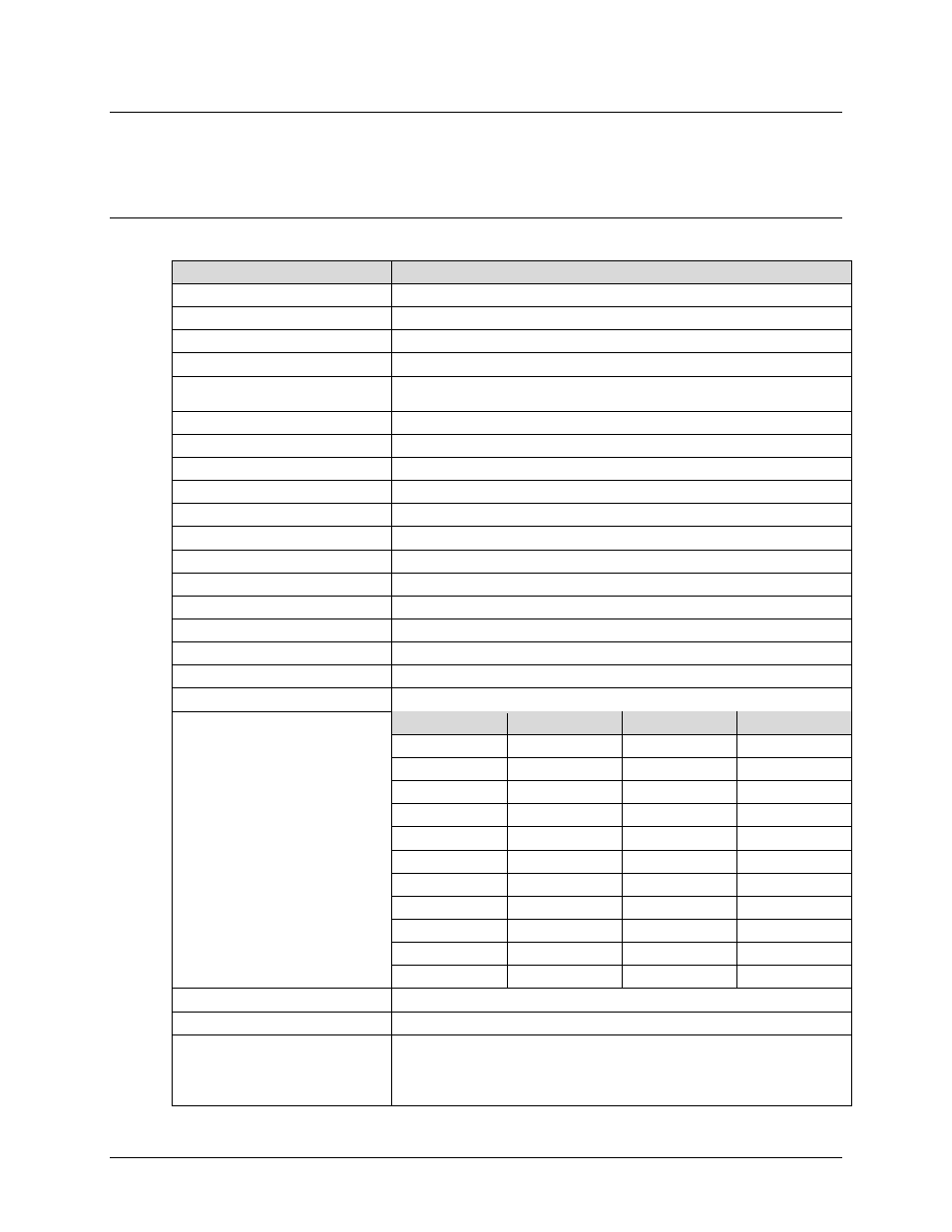
1.4.1.1 Demodulator
Specification
Parameters
Frequency Range
950 to 2150 MHz
Input
Type ‘N’ female connector
Input Impedance
50
Ω, 17 dB minimum return loss
Input Power Range
-130 + 10
log
(symbol rate) to -80 + 10
log
(symbol rate) dBm (see Figure 1-6)
Maximum Composite Operation Level
102 – 10
log
(symbol rate, desired carrier) dBC, +10 dBm max, with the additional
requirement that within ±10 MHz of the desired carrier, composite power is ≤ +30 dBC.
Absolute Maximum, No Damage
+20 dBm
Adaptive Equalizer
5-tap design, selectable on/off
Acquisition Range
Fixed acquisition range of ± Rs/2 = receive symbol rate / 2
Clock Tracking Range
± 100 ppm min
Acquisition Range
+/- 100kHz
Spectral Inversion
Normal or Inverted
Return Loss
min 18dB (typical 20 dB)
Receiver Signal Level Monitor
+/- 6dB (typical)
FEC Mode
VersaFEC – CCM and Return Link ACM
Decapsulation
Streamline
Symbol Rate Range
16Ksps to 4.5 Msps in CCM Mode
Spectral Mask
20%, 25% or 35%.
Data Rate
6Kbps to 15.35 Mbps and corresponds to symbol rate ranges in CCM Mode
Modulation and Code Rate
Modulation
Code Rate
Min (Kbps)
Max. (Kbps)
BPSK 0.488 16.0 2190.0
QPSK 0.533 18.0 4800.0
QPSK 0.631 21.0 5670.0
QPSK 0.706 23.0 6340.0
QPSK 0.803 26.0 7220.0
8-QAM 0.642 31.0 8670.0
8-QAM 0.711 35.0 9600.0
8-QAM 0.780 38.0 10530.0
16-QAM 0.731 47.0
13160.0
16-QAM 0.829 54.0
14910.0
16-QAM 0.853 55.0
15350.0
Descrambling
V.35 or OFF
(FUTURE)
I&Q Constellation
Via Web Server (HTTP) Interface
Monitor Functions
• Eb/No Frequency Offset
• Corrected BER
• Rx signal level
• LNB current and voltage