Maintenance – Beisler 1360-4 User Manual
Page 65
C-25
Service Instructions Automatic Multi-Head Serging Machine1365-4
Beisler GmbH
C.5
Maintenance
C.5.20 Inputs and outputs of the main PCB
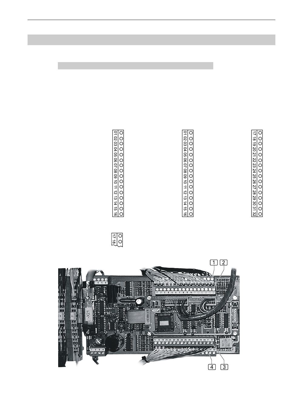
Fig. 19: The inputs and outputs for controlling the machine functions
are connected to the terminal strips X24-X27.
1 X 24 Inputs
2 X 25 Outputs
3 X 26 Outputs
4 X 27 Inputs
X24 Inputs
Swing arm
ES02
Cross transportES01
Bonding clamp
ES04
Bonding start
ES05
Thread monitor A
ES08
Thread monitor B
ES09
Photocell C
ES10
Cont. guide photoc. A ES11
Prog. start photoc. A
ES12
Prog. start photoc. B
ES13
Crs. trnsp. stop photoc ES14
Protect. strap photoc. ES15
Cont. guide photoc. B ES16
X25 Outputs
Pressure foot up A
Y10
Tension blowing A
Y14
Chain cutting A
Y12
Table blowing A
Y13
Dirt aspiration A
Y15
Crs. transp. stamp A
Y09
Cont. guide down A
Y16
Puller down A
Y17
Roller down A Y18
Contour roller A
Y19
Pressure foot up B
Y20
Tension blowing B
Y24
Contour roller B
Y38
Fly blowing B
Y31
Stacker start
Y32
Stacker motion
Y35
X26 Outputs
Chain cutting B
Y22
Table blowing B
Y23
Dirt aspiration B
Y25
Contour guide down B Y26
Puller down B
Y27
Roller down B Y28
Swing arm stamp downY33
Swing arm in
Y34
Transport up A / B
Y36
Support swinging
Y37
Bonding clamp down Y3
Bonding station down Y4
Pressure foot up C
Y1
Chain/Dirt aspiration C
Y5
Puller swinging
Y39
X27 Inputs
Photocell
Y22
Fig. 19