Maintenance – Beisler 1360-4 User Manual
Page 56
C-16
Service Instructions Automatic Multi-Head Serging Machine 1365-4
Beisler GmbH
C.5
Maintenance
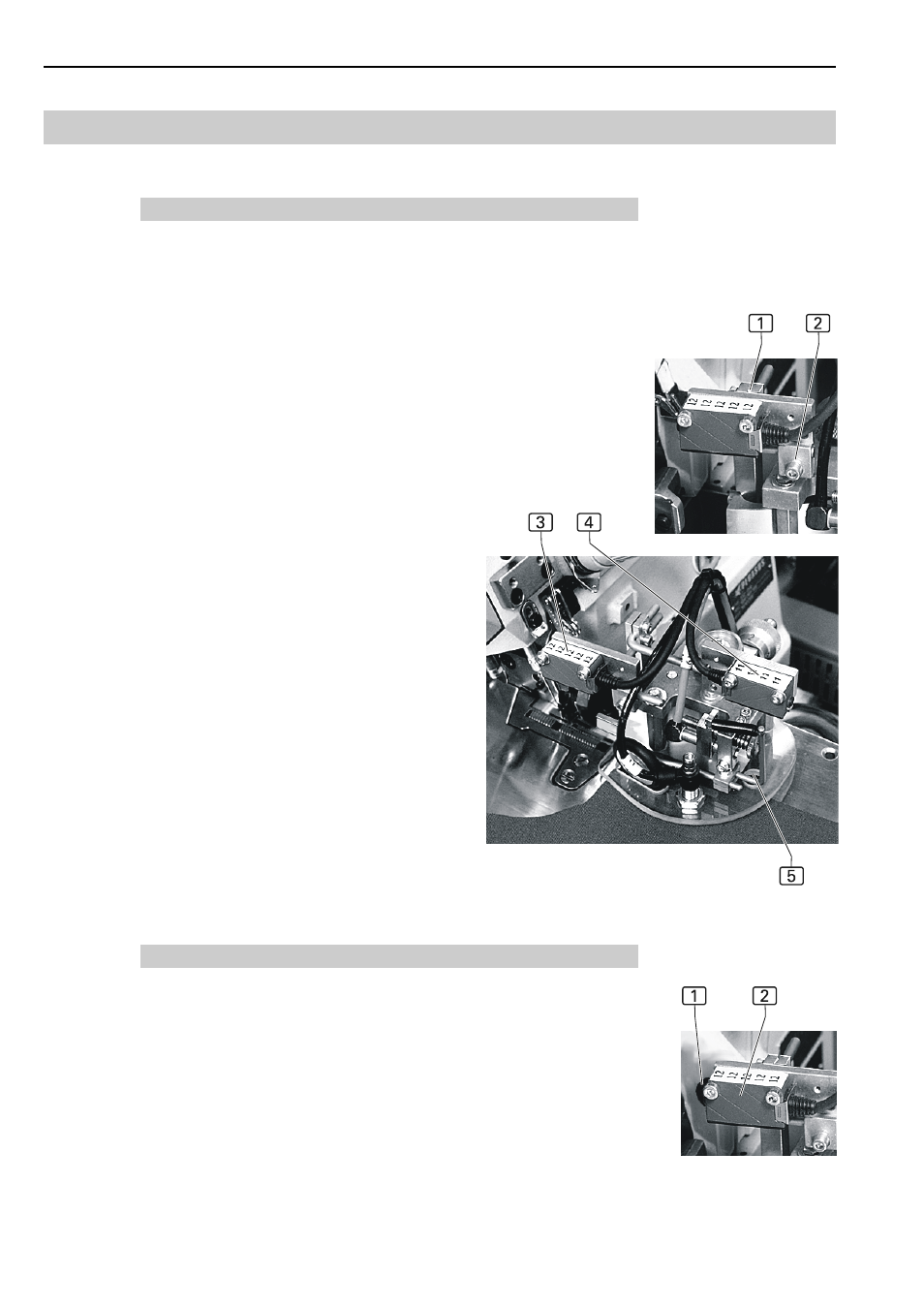
C.5.9 Positioning the contour guide photocells
Fig. 11: Clamp blocks secure the contour guide photocells to the rod
brackets so that the photocell position can be changed in any given di-
rection. The light beam of the photocells should always be positioned to
the center of the corresponding film disk.
To adjust a photocell:
1. To adjust the position in the direction of X: Loosen clamp block loca-
ting screw 1.
2. To adjust the position in the direction of Z: Loosen clamp block loca-
ting screw 2.
3. The light beam of the sewing start photocell 3 is reflected by the
polished surface of the sewing unit.
4. The light beam of the contour guide photocell 4 is reflected by the
film disk through the opening 5 at the sliding plate.
5. Adjust the position of the photocells and tighten the locating screws.
C.5.10 Adjusting the photocell light sensitivity
The sensitivity of the photocells must be adjusted in accordance with
the sewing material used. The adjustment is made using a white cloth
at the photocell that starts the sewing process.
1. Fig. 9: Ensure that the light beam of the photocell 2 is not interrup-
ted by objects.
2. Adjust the sensitivity so that the light beam recognizes the white
cloth when it is moved into the sensor area.
3. Rotate potentiometer 1 at the photocell face counterclockwise to
minimize the sensitivity.
4. Increase sensitivity gradually; after each change, move white cloth
into sensor area. When the sensitivity threshold limit is reached, the
photocell darkens, and the machine cycle starts.
Fig. 8
Fig. 9