Assembling the controller, Adjusting the pedal positions – Baby Lock Destiny (BLDY) Instruction & Reference Guide-Part1 User Manual
Page 28
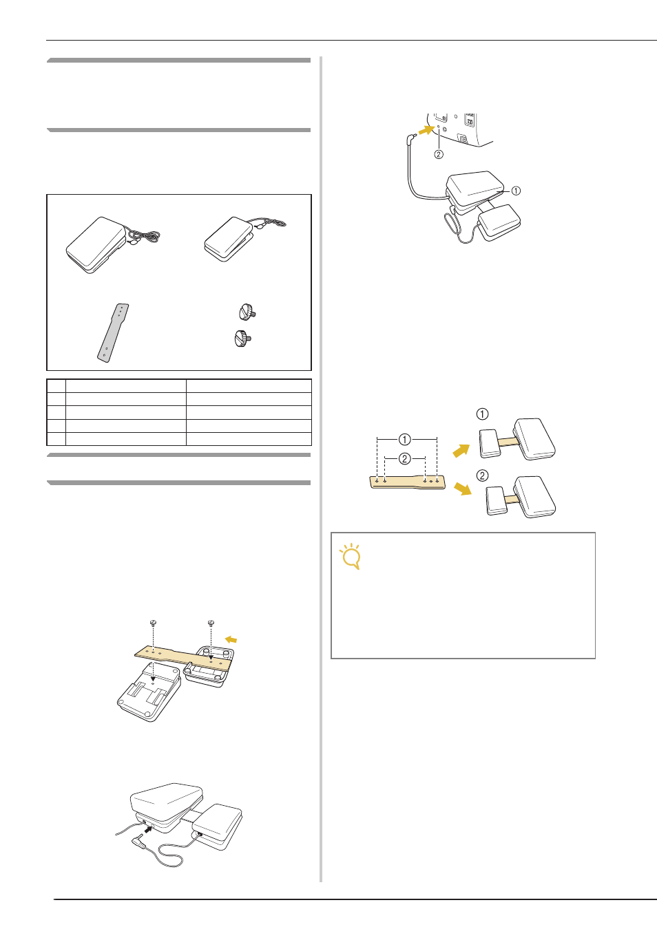
NAMES OF MACHINE PARTS AND THEIR FUNCTIONS
26
Using the Multi-function Foot
Controller (Only for supplied
models)
Refer to see “Specifying the Multi-Function Foot
Controller (Only for supplied models)” on page
82, before using this foot controller.
Assembling the Controller
a
Align the wide side of the mounting plate
with the notch in the bottom of the main
foot controller, and then secure them
together with a screw.
Feed the other side of the mounting plate into the
notch on the bottom of the side pedal, and then secure
them together with a screw.
b
Insert the plug for the side pedal into the
jack at the back of the main foot controller.
c
Insert the plug for the main foot controller
into the foot controller jack on the right
side of the machine.
a Multi-function foot controller
b Foot controller jack
■ Adjusting the Pedal Positions
The pedal spacing can be adjusted depending on
the screw holes used in the mounting plate. The
pedal spacing is the widest when the pedals are
attached using the outermost screw holes
a
; the
pedal spacing is the narrowest when they are
attached using the innermost screw holes
b
.
1
2
3
4
No.
Part Name
Part Code
1
Main foot controller
XF6709-201
2
Side pedal
XF3217-001
3
Mounting plate
XF3222-001
4
Mounting screw × 2
XF3223-001
Note
• The side pedal may be attached on the right
or left side of the main foot controller.
• For greater distance you always have the
option of not connecting the side pedal and
main foot controller using the mounting
plate, making sure that both pedals are
connected using the jack from the side
pedal to the main foot controller.