AMETEK 2003RP User Manual
Page 83
The SCPI Command Tree
As previously explained, the basic SCPI communication method involves sending one or
more properly formatted commands from the SCPI command tree to the instrument as
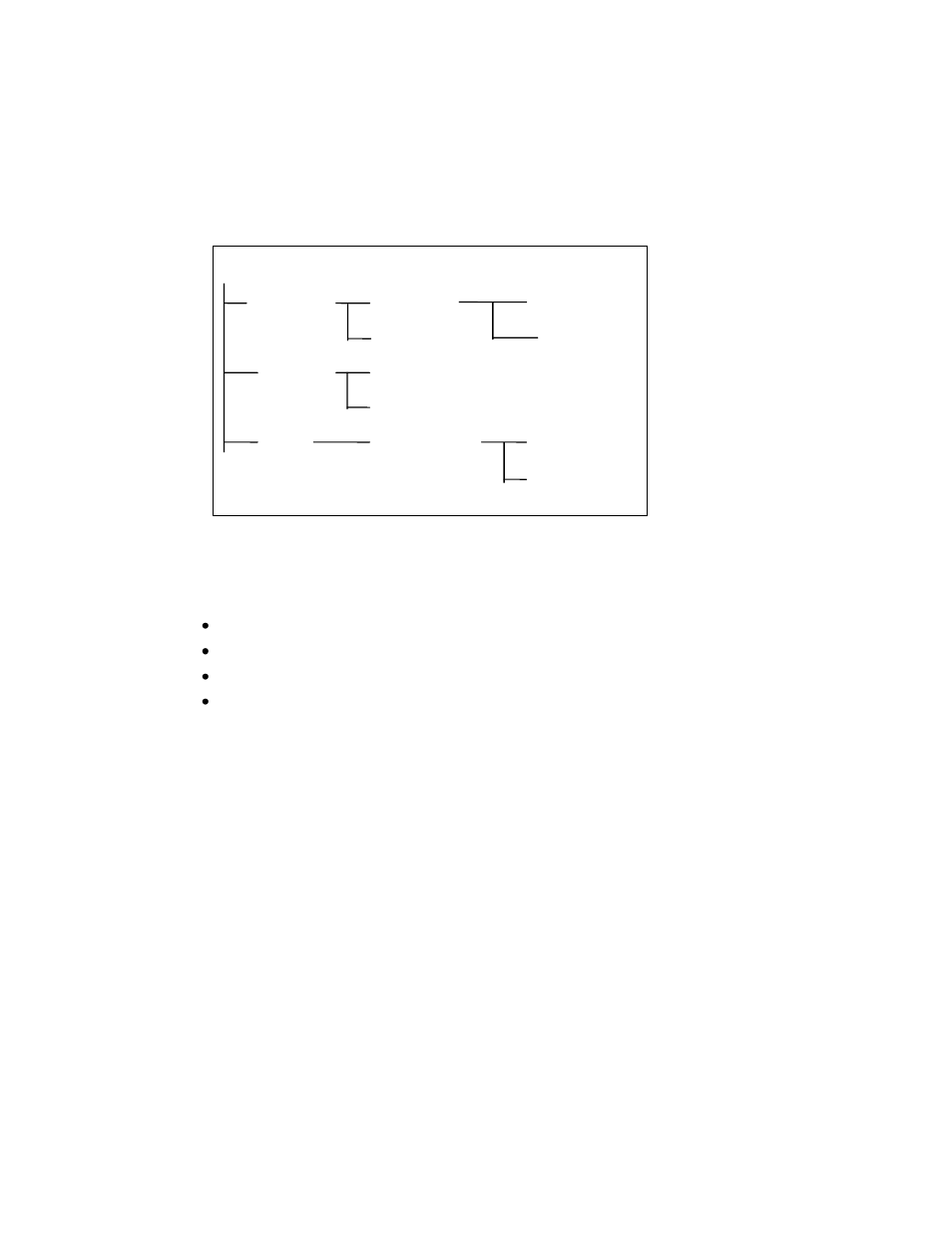
program messages. The following figure shows a portion of a subsystem command tree,
from which you access the commands located along the various paths (you can see the
complete tree in appendix A).
Root
[:SOURce]
:VOLTage
[:LEVel]
:CURRent
:RANGe
:SYSTem
:REMote
:ERRor
:LIMit
:FREQuency
:LOW?
:HIGH?
Figure 9-1: Partial Command Tree
The Root Level
Note the location of the ROOT node at the top of the tree. Commands at the root level are at
the top level of the command tree. The SCPI interface is at this location when:
the AC source is powered on
a device clear (DCL) is sent to the AC source
the SCPI interface encounters a message terminator
the SCPI interface encounters a root specifier
Active Header Path
In order to properly traverse the command tree, you must understand the concept of the
active header path. When the AC source is turned on (or under any of the other conditions
listed above), the active path is at the root. That means the SCPI interface is ready to accept
any command at the root level, such as SOURCe or MEASurement.
If you enter SOURCe the active header path moves one colon to the right. The interface is
now ready to accept :VOLTage :FREQuency, or :CURRent as the next header. You must
include the colon, because it is required between headers.
If you now enter :VOLTage, the active path again moves one colon to the right. The interface
is now ready to accept either :RANGe or :LEVel as the next header.
If you now enter :RANGe you have reached the end of the command string. The active
header path remains at :RANGe If you wished, you could have entered :RANGe 150 ;LEVel
115 and it would be accepted as a compound message consisting of:
1. SOUR:VOLT:RANG 150.
2. SOUR:VOLT:LEV 115.