AMETEK 2003RP User Manual
Page 20
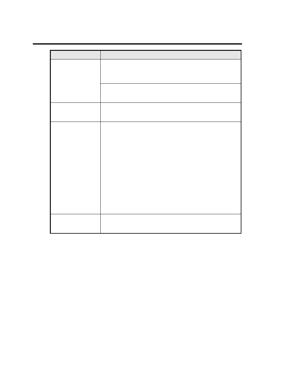
2.9 Front Panel Controls
Parameter
Specification
Controls:
Knobs:
Two knobs allow continuous change of voltage, frequency and
current limit for all three phase outputs. Voltage change is
inactive on single voltage range configuration units.
Function keys:
Keys control output state, voltage range, 7 segment LED Display
mode and selected phase for liquid crystal display.
Displays:
Two, 4 digit, 0.5” 7 segment LED:
For viewing programmed voltage, frequency, current limit for all
phases or for displaying measured current on selected phase.
Status Indicators:
13 LED‟s:
HIGH (voltage range)
AUTO (voltage range)
FREQ (frequency display)
I RMS (rms current display)
I PK (peak current display)
PWR (power display)
PF (power factor display)
A (phase selected for display)
B (phase selected for display)
C (phase selected for display)
FAULT (of output voltage)
REMOTE (interface active)
OUTPUT (on, relay closed)
(refer also to paragraph 4.1.1)
Phase Selection:
The phase selection and indication applies to the measurement
readouts only. Settings of voltage, frequency and current made
using the rotary knobs apply to all three phases.