Wiring, General wiring guidelines, Mechanical connection of the base modules – Pilz PSSu E F PS User Manual
Page 27: 6wiring, 1 general wiring guidelines, 1 mechanical connection of the base modules
Pilz GmbH & Co. KG, Felix-Wankel-Straße 2, 73760 Ostfildern, Germany
Telephone: +49 711 3409-0, Telefax: +49 711 3409-133, E-Mail: [email protected]
6-1
6.1
General wiring guidelines
6
Wiring
6
6000
Wiring
Wiring
6-
6.1
General wiring guidelines
6100
General wiring guidelines
6-
][Verdrahtung BA Einleitung
Please note:
][Verdrahtung Kopf Versorgung
The requirements of the supply voltages can be found in the chapter
entitled "Technical Details".
Safe electrical isolation must be ensured for the external power sup-
plies that generate the supply voltages. Failure to do so could result
in electric shock.
The external power supplies must comply with the current applicable
standard EN 60950-1, EN 61140, EN 50178 or EN 61558-1.
The maximum current load for the periphery supply on the module
bus is 10 A. Please refer to the derating diagram in the chapter enti-
tled "Function Description".
The maximum current load for the C-rail is 10 A. Please refer to the
derating diagram in the chapter entitled "Function Description".
Permitted infeed at the C-rail:
– PE
– 0 V
– Shield
– - 30 VDC ... +30 VDC
– - 48 VAC ... + 48 VAC
Earth the 0 V supply on the periphery supply or monitor each supply
group for earth faults.
The connection of the 0 V supply to the central earth bar or earth fault
monitor must be in accordance with the relevant national regulations
(e.g. EN 60204-1, NFPA 79:17-7, NEC: Article 250).
Details of the minimum range for cable cross sections on connection
terminals can be found in the section entitled "Technical Details".
Use copper wiring.
6.1.1
Mechanical connection of the base modules
Mechanical connection of the base modules
6-
][Modulverdrahtung mech
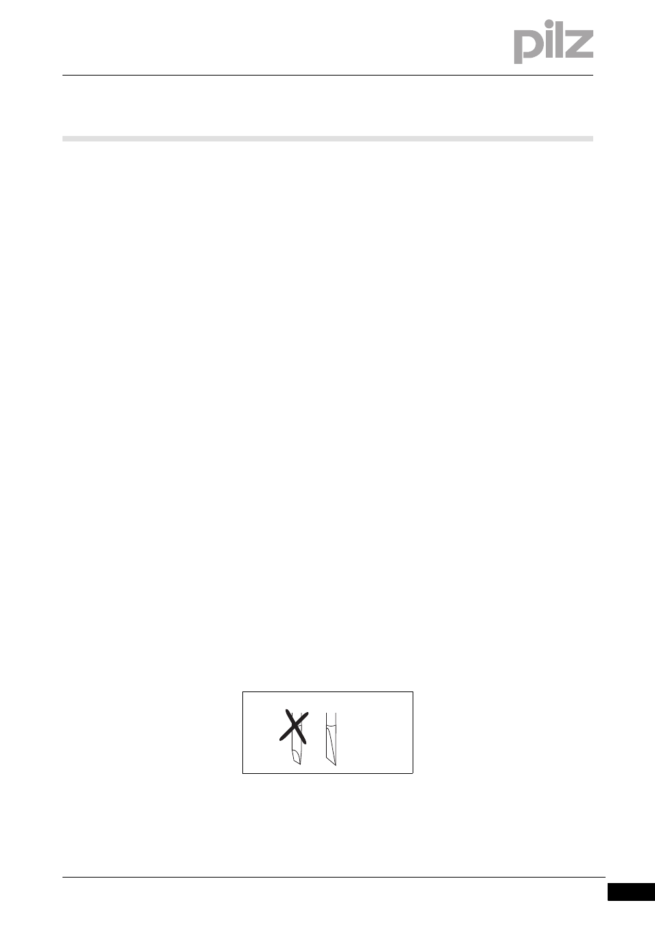
Procedure:
Use a flat blade screwdriver (DIN 5264-A)!
Strip the wire back 8 mm.
If necessary, label the connection level with a colour marker [3].
DIN 5264-A