Vortech 2006-2010 6.1L Jeep SRT8 User Manual
Page 16
P/N: 4CK020-010 v6.0, 02/17/2012
©2012 Vortech Engineering, Inc.
All Rights Reserved, Intl. Copr. Secured
6
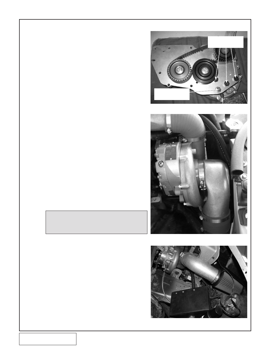
A. Loosen the two bolts installed behind the
supercharger pulley by hand until the bolt
heads contact the supercharger pulley. Slide
the bolt shoulders into the receiving slots in
the supercharger mounting plate keeping the
washers next to the bolt heads. Guide the
cog belt around the supercharger pulley.
B. Install the three 12mm thin-head bolts
through the plate and into the lower part of
the supercharger. Do not use washers.
C. Install the 3/8" X 3" long bolt through the
supercharger mounting plate, a 1.81" spacer
and into the supercharger gearcase using the
supplied washer (See Fig. 5-a).
D. Tighten all six supercharger mounting bolts.
E. Verify that the bearing snap ring on the sup-
plied aluminum idler is pointing towards the
mounting plate and the .375” spacer. Secure
it to the slot in the supercharger mounting
plate using the supplied 12mm hardware.
F. Verify that the supplied cog belt is routed
around both cog pulleys and above the
smooth idler and tighten the idler so that the
gilmer belt is snug (See Fig. 5-a).
G. Secure the remote drain hose away from the
belt and hoses using tie-wraps.
H. Remove 3 forward most plastic rivets and the
forward most reusable rivet holding passen-
ger side inner fender liner to fender. Bend
back inner fender liner to gain access to
wheel well area.
I.
Be sure the supplied inlet duct to the super-
charger inlet is oriented properly and tighten
T-bolt clamp (See Fig. 5-b)
J. Using the supplie d 90° barbed fitting, attach
the supplied ½” breather hose to the hole in
the end-cap of the air filter. Route the ½”
hose to the driver side valve cover and attach
to the breather port.
K. Install the air filter and air filter shield onto the
long end of 3.5-inch pipe and install using 2
#56 clamps and 3.5-inch coupler to air inlet
duct, orient for best clearance and tighten
clamps on each connection.
5.
SUPERCHARGER INSTALLATION
Fig. 5-b
Fig. 5-c
Fig. 5-a (Shown off the vehicle for clarity)
M12 THIN HEAD WITH-
OUT WASHER
3/8 BOLT INSTALLED IN
COUNTERBORED HOLE
NOTE: Use caution when rotating the aluminum inlet duct.
Careful heating with a propane torch will allow for easi-
er rotation without galling the aluminum mating surfac-
es.