Vortech 2006-2010 6.1L Jeep SRT8 User Manual
Page 12
P/N: 4CK020-010 v6.0, 02/17/2012
©2012 Vortech Engineering, Inc.
All Rights Reserved, Intl. Copr. Secured
2
A. Remove the crankshaft damper bolt. (A fac-
tory tool may be used to keep the engine
from rotating or carefully use a pry tool to
keep the damper from rotating.)
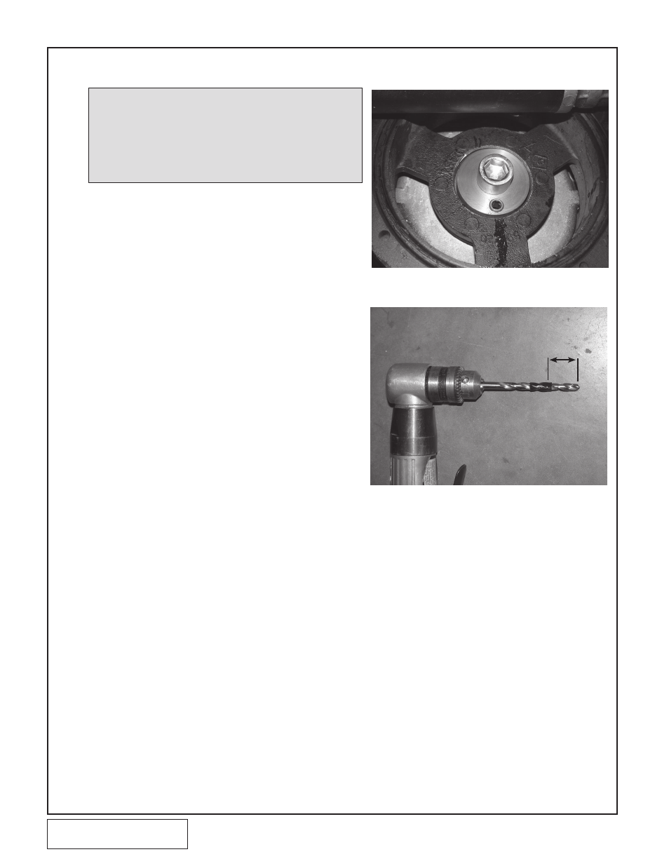
B. Install the supplied drill guide with the raised
section piloting in the damper bore. Secure
in place by installing the supplied socket head
cap screw. Do not over-tighten the screw as
it may distort the drill guide (its purpose is just
to hold the guide in place while drilling). See
Fig. 2-a.
C. Using a small drill motor (right angle pneu-
matic works well), mark a 1/4” drill bit with
electrical tape or a drill stop so that the hole
will be deep enough for the supplied 1/2” long
dowel pin. See Fig. 2-b.
D. Drill hole in damper/crankshaft.
E. Remove the socket head cap screw.
F. Clean area of metal chips and install the sup-
plied dowel pin in the drilled hole making sure
that it does not protrude past the damper
face.
G. Install and tighten the crankshaft damper bolt
to 129 ft-lbs (176 Nm).
2.
HARMONIC DAMPER DOWEL PIN INSTALLATION
Fig. 2-a
Fig. 2-b
1” MINIMUM
NOTE: The purpose of this section is to provide access to the har-
monic damper bolt area so that the crankshaft can be pinned
to the damper to prevent the damper from spinning on the
crankshaft. The following steps will work on all or most appli-
cations. If it is not possible to get adequate clearance by per-
forming the following steps, follow the manufacturer’s steps
for removing the harmonic damper until there is sufficient
room to work in.