Vortech 2006-2010 6.1L Jeep SRT8 User Manual
Page 14
P/N: 4CK020-010 v6.0, 02/17/2012
©2012 Vortech Engineering, Inc.
All Rights Reserved, Intl. Copr. Secured
4
A. Drain the engine coolant into a clean pan for
later use.
B. Remove the two bolts securing the thermostat
housing and set all aside.
C. Remove the alternator bolt. Loosely install
the supplied M10 stud in its place.
D. Cut off plastic wire loom push connector and
discard (see Fig. 4-a).
E. Loosen the wire loom on top of the valve
cover so that the primary mounting plate can
be installed flush with the front face of the
head.
F. Temporarily unplug the wires to the alternator
if necessary. Cut the wire loom and separate
the alternator wires so that they will reach the
alternator.
G. Loosely attach the primary mounting plate to
the head with the recess pointed back using
the supplied 8mm hardware as shown in Fig.
4-b.
H. With the cog belt encircling the cog pulley,
slide the slotted portion of the supercharger
mounting plate assembly onto the 100mm
bolt already installed and loosely attach it to
the primary mounting plate using the 8mm
hardware as shown in Fig. 4-d.
I.
Sandwich the supplied 1.97” spacers between
the two plates at every location where there is
a hole in the primary mounting plate. Note
that one of the spacers has a flat and must
be used in the lowermost hole to clear the
water pump housing (See Fig. 4-b, 4-c).
J. Be sure to keep alt wiring loom below bracket
and spacers to prevent from contacting cog
drive. Use the supplied 5/16 x 6.75” long
studs and 2.9" spacers at the location shown
in Fig. 4-e.
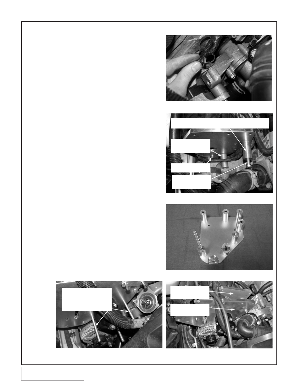
4.
SUPERCHARGER MOUNTING PLATE INSTALLATION
Fig. 4-b
M8 X 20MM (TIGHTEN
FULLY AT THIS TIME)
M8 X 100MM (INSTALL
LOOSELY FOR PLATE
ALIGNMENT)
SPACER WITH FLAT
(SHOWN PLACED IN
POSITION)
Fig. 4-d
Fig. 4-e
Fig. 4-a
SPACER IN FRONT OF PLATE - .45" SPACER BETWEEN PLATE
AND HEAD AT THIS LOCATION ONLY
Fig. 4-c
SUPERCHARGER
MOUNTING PLATE
PRIMARY MOUNTING
PLATE
5/16X6.75" STUDS GO THRU
BOTH PLATES WITH A 1.97"
SPACER IN BETWEEN
(2.9" SPACERS NOT SHOWN)