Equivalent schematic and connection diagrams, Dual-in-line and small outline packages – Elenco AM/FM Radio Kit User Manual
Page 8
This radio kit contains two separate audio
systems. The first is an integrated circuit (IC) and
the second is a five-transistor circuit. The objective
is to show you how these two circuits function and
to compare the performance of each. We will
begin the radio project by building the IC audio
amplifier first.
The purpose of the Audio Amplifier is to increase
the audio power to a level sufficient to drive an 8
ohm speaker. To do this, DC (direct current) from
the battery is converted by the amplifier to an AC
(alternating current) in the speaker. The ratio of
the power delivered to the speaker and the power
taken from the battery is the efficiency of the
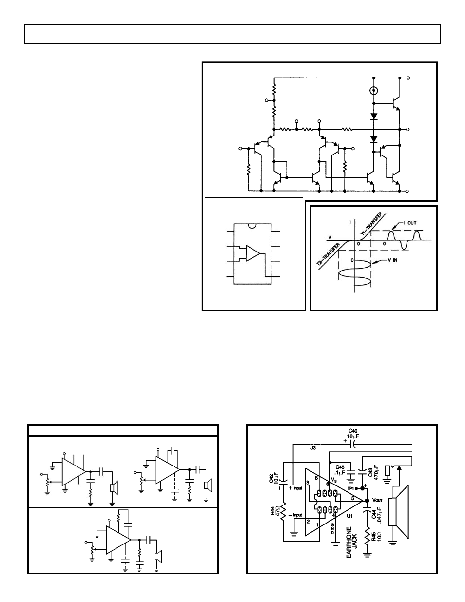
amplifier. For the Audio Amplifier, we use the
integrated circuit (IC) LM-386. In Figure 2, you can
see equivalent schematic and connection
diagrams.
In a Class A amplifier (transistor on over entire
cycle), the maximum theoretical efficiency is 0.5
or 50%. But, in a Class B amplifier (transistor on
for 1/2 cycle), the maximum theoretical efficiency
is 0.785 or 78.5%. Since transistor characteristics
are not ideal in a pure Class B amplifier, the
transistors will introduce crossover distortion. This
is due to the non-linear transfer curve near zero
current or cutoff. This type of distortion is shown in
Figure 3.
In order to eliminate crossover distortion and maximize
efficiency, the transistors of the audio amplifier circuit are
biased on for slightly more than 1/2 of the cycle, Class AB.
In other words, the transistors are working as Class A
amplifiers for very small levels of power to the speaker, but
they slide toward Class B operation at larger power levels.
To make the LM-386 a more versatile amplifier, two pins (1
and 8) are provided for gain control. With pins 1 and 8 open,
the 1.35k
Ω
resistor sets the gain at 20 (see Figure 4a). The
gain will go up to 200 (see Figure 4b) if a capacitor is
placed between pins 1 and 8. The gain can be set to any
value from 20 to 200 if a resistor is placed in series with the
capacitor. The amplifier with a gain of 150 is shown in
Figure 4c.
The amplifier in our kit with a gain of 150 is shown in
Figure 5. Capacitor C40 couples the audio signal from the
volume control to the input of the audio amplifier.
Capacitor C43 blocks the DC to the speaker, while
allowing the AC to pass.
-7-
SECTION 1A
INTEGRATED CIRCUIT (IC) AUDIO AMPLIFIER
Figure 3
Figure 2
Figure 4a
Figure 4c
Figure 4b
Figure 5
Typical Applications
Amplifier with Gain = 20
Minimum Parts
V
IN
V
S
2
6
1
8
5
7
4
LM386
+
+
–
.05
μ
F
10
Ω
10k
Ω
Amplifier with Gain = 150
Amplifier with Gain = 200
3
V
IN
V
S
2
6
1
8
5
7
4
LM386
+
–
10k
Ω
3
+
.05
μ
F
10
Ω
BYPASS
+
10
μ
F
V
IN
V
S
2
6
1
8
5
7
4
LM386
+
–
10k
Ω
3
.05
μ
F
10
Ω
BYPASS
47
Ω
10
μ
F
+
+
Equivalent Schematic and Connection Diagrams
V
OUT
V
S
6
5
7
4
15k
Ω
BYPASS
GND
15k
Ω
2
– INPUT
150
Ω
1.35k
Ω
8
GAIN
1
GAIN
15k
Ω
50k
Ω
50k
Ω
+ INPUT
Dual-In-Line and Small
Outline Packages
Top View
GAIN
– INPUT
+ INPUT
GND
GAIN
BYPASS
V
S
V
OUT
4
1
2
3
5
8
7
6
3