Elenco AM/FM Radio Kit User Manual
Page 22
Slowly decrease the frequency of the generator until
the output drops to 0.7 of its original reading, 1.4Vpp or
2.8 divisions. This frequency is called the low frequency
3dB corner - the low frequency 3dB corner or (f high
3dB) - (f low 3dB). Your calculated answer should be
greater than 30kHz.
DISTORTION
Connect the generator and oscilloscope as shown in
Figure 18. Set the generator at a frequency of 1kHz,
turn the power ON and turn the volume to maximum.
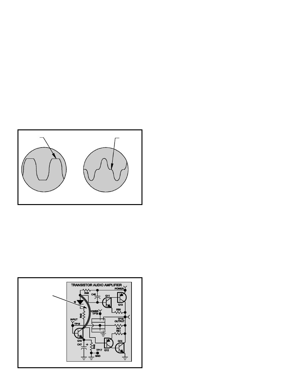
Adjust the generator output until the peaks of the
sinewave at TP19 are clipped as shown in Figure 19A.
One side of the sinewave may clip before the other
depending on the DC centering at TP19. If oscillations
are seen, connect a clip lead from the GND of your
generator to the GND of the circuit.
Measure the maximum voltage peak to peak when
clipping first occurs and record that value here:
Vclp = _______ Vpp.
Using a wire short out diode D5 and resistor R49 as
shown in Figure 20. The waveform should resemble
Figure 19B. The “flat spots” near the center of each
sinewave demonstrate what is called crossover
distortion. Most of this distortion should disappear when
you remove the shorting lead. Turn the power OFF.
MAXIMUM POWER OUTPUT
The maximum power output before distortion due to
“clipping” can be calculated using the voltage Vclp
obtained in step 4 as follows:
Vpeak (Vp) = Vclp/2
Vroot mean squared (Vrms) = Vp x 0.7
Max power out = (Vrms)
2
/8 ohms = (Vclp x 0.35)
2
/8
Maximum power output should be greater than 350
milliwatts.
EFFICIENCY
By measuring the DC power taken from the battery at
the maximum power output level, the efficiency to the
audio amplifier can be calculated. Power from the
battery is equal to the current taken from the battery
times the voltage of the battery during maximum power
output. Efficiency can then be calculated as follows: Eff
= Max audio power/Battery power. It is best to use a
power supply (if available) to prevent supply voltage
from changing during these measurements. Connect
the generator, oscilloscope and current meter as shown
in Figure 21. Set your current meter to read 1 amp DC.
Turn the power ON and rotate the volume control to
maximum. Slowly increase the amplitude of the audio
generator until the output is clipped as shown in Figure
19A. Record Vclp here:
Vclp = _________ Vpp.
This should be equal to Vclp in step 4. Record the DC
current drawn from the 9 volt supply here:
Current (I) max = ________ Amps.
Measure the supply voltage and record the V supply
here:
V supply = ________ volts.
Turn the power OFF. Calculate the maximum power
output as done in the Maximum Power Output Step.
Record your answers on the following page.
-21-
Figure 19
A
B
Clipped
Crossover
Distortion
Figure 20
Wire lead or
clip lead